Applied Physics
Vol.4 No.11(2014), Article
ID:14305,7
pages
DOI:10.12677/APP.2014.411022
Study on Flash Evaporation Performance of Marine Flash Tank
1Navy Military Delegate Room of Wuhan 701 Research Institute, Wuhan
2China Ship Development and Design Center, Wuhan
Email: *long31609@163.com
Copyright © 2014 by authors and Hans Publishers Inc.
This work is licensed under the Creative Commons Attribution International License (CC BY).
http://creativecommons.org/licenses/by/4.0/


Received: Sep. 12th, 2014; revised: Oct. 9th, 2014; accepted: Oct. 14th, 2014
ABSTRACT
Taken marine flash tank as the prototype, the variable mass system thermodynamics model of flash tank was built based on the reasonable assumptions. The simulation program was compiled based on Simulink code. Study on flash evaporation performance for marine flash tank was conducted at different operating conditions and rules of variation of the key thermal-hydraulic parameters were obtained. Simulation results revealed that the change rate of fluid temperature increased due to lower initial temperature and higher superheat. Meanwhile, the results, which were obtained in different backpressure and initial temperature, agreed well with experimental data. The maximum relative deviation arrived at 5%. The successful application of variable mass system thermodynamics model in the simulation of the flash tank performance can supply some theoretical basis for ship steam power system design.
Keywords:Flash Evaporation, Numerical Simulation, Flash Tank, Steam Power

船用闪蒸罐闪蒸性能仿真研究
王剑平1,杨元龙2*
1海军驻武汉701所军事代表室,武汉
2中国舰船研究设计中心,武汉
Email: *long31609@163.com
收稿日期:2014年9月12日;修回日期:2014年10月9日;录用日期:2014年10月14日

摘 要
以船用闪蒸罐为原型,在合理假设基础上,建立了闪蒸罐变质量系统热力学模型。采用Simulink搭建闪蒸仿真程序,进行了不同运行工况下船用闪蒸罐闪蒸性能仿真研究,仿真结果表明随着闪蒸罐初始水温下降,过热度增加,闪蒸过程中流体温度变化率增大。在不同背压和初始温度下得到的压力和温度变化规律与试验值吻合较好,最大相对偏差为5%。变质量系统热力学模型在闪蒸罐闪蒸性能仿真计算中的成功应用,可为船舶蒸汽动力系统设计提供一定的理论依据。
关键词
闪蒸,数值仿真,闪蒸罐,蒸汽动力

1. 引言
闪蒸现象普遍存在于船用蒸汽动力系统中,因其汽液两相流动与传热耦合求解计算的复杂性使其一直是研究较活跃的课题之一。船用闪蒸罐内流体闪蒸过程,常伴有传热传质、流型转换、汽液两相流动沸腾现象的发生[1] -[3] ,明显地改变工质热工水力特性,对船用蒸汽系统的闪蒸效率和运行性能造成了很大影响。因此,船用闪蒸罐的闪蒸性能就成为船用蒸汽动力系统性能研究和设计中的难点。
目前闪蒸罐的仿真计算大多采用热力系统的集总参数法,集中于汽液两相热力学平衡模型的研究[4] -[8] 。公开文献中有关采用变质量系统热力学模型对船用闪蒸罐进行数值仿真研究的报道至今尚未见到。因此,以探索闪蒸罐闪蒸的数值计算方法为目的,通过数值仿真研究船用闪蒸罐的闪蒸过程,研究不同工况下闪蒸罐压力、温度等热工水力参数的分布规律及影响因素,从而为闪蒸罐的热工结构、运行参数的优化设计及船用蒸汽动力系统设计提供参考依据。
2. 数值计算方法
2.1. 闪蒸罐运行状况及物理模型
闪蒸罐结构示意如图1所示。水从闪蒸罐进水口进入闪蒸罐,过热蒸汽自进汽口将闪蒸罐内工质加

Figure 1. Flash tank diagram
图1. 闪蒸罐简图
热至所需的初始温度,停止充入汽,闪蒸后蒸汽由闪蒸罐出口流出。
2.2. 变质量系统热力学模型
考虑到船用闪蒸罐工作条件及实际运行过程,为建立闪蒸罐变质量系统热力学模型,提出以下简化假设:
1) 不考虑加热蒸汽进入闪蒸罐的喷射过程,忽略蒸汽流动等引起的能量耗散;
2) 忽略闪蒸罐的散热损失;
3) 认为汽、液两相的压力相同且温度不同,处于热力学不平衡状态;
4) 忽略开关放汽阀的影响。
基于上述数学建模的简化条件,以闪蒸罐为研究对象,运用集总参数法及热力学状态参数方程,建立闪蒸罐变质量系统热力学模型如下:
水相连续性方程为:
 (1)
(1)
水相能量守恒方程为:
 (2)
(2)
汽相连续性方程为:
 (3)
(3)
汽相能量守恒方程为:
 (4)
(4)
式中, 为水的质量,单位为kg;
 为水的蒸发率,单位为kg/s;
 为水的比焓,单位为kJ/kg;
 为当前压力下饱和汽体的比焓,单位为kJ/kg;
 为水的比容,单位为m3/kg;
![]() 为压力,单位Pa;
为压力,单位Pa; 为时间,单位为s;
 为汽体的质量,单位为kg;
![]() 为汽体的比焓,单位为kJ/kg;
为汽体的比焓,单位为kJ/kg; 为工质边界流动引起的汽体流量净增量,单位为kg/s;
![]() 为汽体的比容,单位为m3/kg。
为汽体的比容,单位为m3/kg。
其中液相水的蒸发率[9] 计算得:
 (5)
(5)
式中, 为当前压力下饱和水的比焓,单位为kJ/kg;
 为蒸发弛豫时间因子,单位为s;
 为当前压力下水的汽化潜热,单位为kJ/kg。
根据闪蒸罐的体积守恒可知:
 (6)
(6)
式中,![]() 为闪蒸罐的体积,单位为m3。
为闪蒸罐的体积,单位为m3。
基于热力学状态参数方程可知:
 (7)
(7)
 (8)
(8)
将式(7)代入式(6),整理得:
 (9)
(9)
将式(2)和(4)代入(9)式,得到闪蒸罐的压力变化率为:
 (10)
(10)
3. 边界条件
结合船用闪蒸罐不同工况下的运行参数,建立边界条件如下:①初始压力为0.1 MPa;②初始水位高度为350 mm;③初始水质量为8.5 kg;④出气口直径为40 mm;⑤计算时间为80 s;⑥工况1:初始温度86℃,背压50 KPa;⑦工况2:初始温度86℃,背压40 KPa;⑧工况3:初始温度90℃,过热度4℃;⑨工况4:初始温度80℃,过热度4℃。
4. 动态仿真结果及分析
基于汽液两相变质量系统热力学模型,采用Simulink搭建闪蒸仿真程序(如图2所示),进行了不同运行工况下船用闪蒸罐闪蒸性能仿真研究,得到闪蒸罐压力、温度等热工水力参数。
4.1. 不同背压下闪蒸性能分析
图3给出了初始温度为86℃,背压为50 KPa工况下闪蒸罐压力随时间的变化曲线。
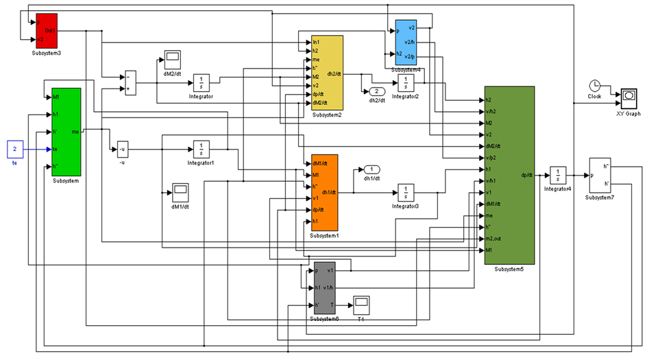
Figure 2. Diagram of simulation model
图2. 仿真模型简图
从图中可以看出,非平衡模型仿真计算与实验得到的闪蒸罐压力曲线变化趋势基本保持一致,均呈现快速下降再稳定不变的分布规律。
从图中还可以看出,闪蒸罐压力快速降低,再呈现短暂的平稳过渡段,最终压力不断降低并保持稳定不变。主要原因是试验中闪蒸初始阶段闪蒸非常剧烈,而闪蒸罐出口很小(直径为40 mm),打开放汽阀瞬间闪蒸汽体不能瞬时排出罐体,导致压力出现过渡状态,随着闪蒸的进行,水体过热度降低,蒸发速率低于蒸汽的排放速率,压力快速下降至背压。
图4示出了初始温度为86℃,背压为50 KPa工况下闪蒸罐温度随时间变化曲线。由图4可知,闪蒸罐温度急剧下降至稳定不变。究其原因主要是压力快速下降,闪蒸过程产生剧烈的沸腾蒸发现象,进而导致闪蒸罐工质温度急剧降低。仿真计算值与实验值[10] 相对偏差约为±2%。
仿真计算的初始温度为86℃,背压为40 KPa工况下闪蒸罐内部压力的变化规律如图5所示。随着剧烈闪蒸过程的发生,闪蒸罐压力快速降低,达到背压值。如图6所示,初始温度为86℃,背压为40 KPa

Figure 3. Pressure curves for the initial temperature at 86˚C and backpressure at 50 KPa
图3. 初始温度86℃,背压50 KPa工况下压力曲线
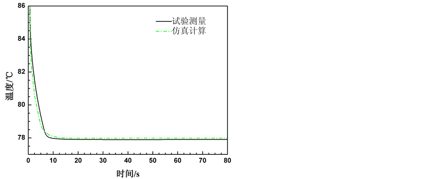
Figure 4. Temperature curves for the initial temperature at 86˚C and backpressure at 50 KPa
图4. 初始温度86℃,背压50 KPa工况下温度曲线
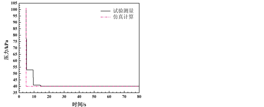
Figure 5. Pressure curves for the initial temperature at 86˚C and backpressure at 40 KPa
图5. 初始温度86℃,背压40 KPa工况压力曲线
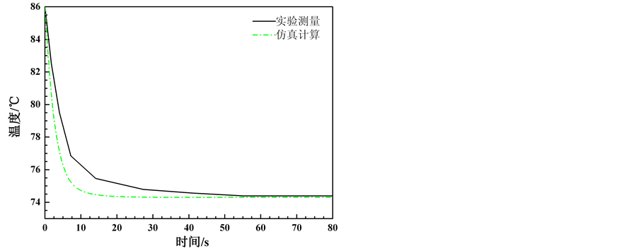
Figure 6. Temperature curves for the initial temperature at 86˚C and backpressure at 40 KPa
图6. 初始温度86℃,背压40 KPa工况温度曲线
工况下闪蒸罐温度呈快速下降的变化规律。另外,随着闪蒸罐出口背压下降,仿真计算的温度与实验数值偏差增大,此工况下仿真与实验值[10] 相对偏差达到5%。
4.2. 不同初始温度下闪蒸性能分析
图7给出了初始温度为90℃,过热度为4℃工况下闪蒸罐压力变化曲线。由图7可知,由于闪蒸过程中沸腾蒸发速率与汽体排出率动态平衡的作用,导致试验得到的压力变化曲线呈阶梯式快速下降,且仿真与实验[10] 压力值吻合较好。
由图8可知,在内外压差作用下,产生剧烈的闪蒸过程,导致工质温度快速下降。随着内外压差平衡,闪蒸程度减缓,工质温度趋于稳定不变状态。
图9、图10示出了初始温度80℃,过热度4℃工况下闪蒸罐压力和温度分布曲线。由图8、图9可知,基于非平衡热力学模型的仿真计算值与试验值吻合较好。从图8与图10对比,随着闪蒸罐初始水温下降,过热度增加,工质温度变化率增大,闪蒸停止后温度略有降低。
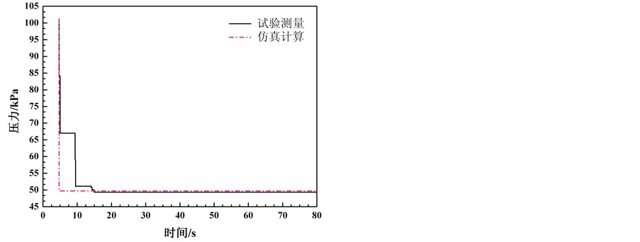
Figure 7. Pressure curves for the initial temperature at 90˚C and superheat at 4˚C
图7. 初始温度90℃,过热度4℃工况下压力曲线
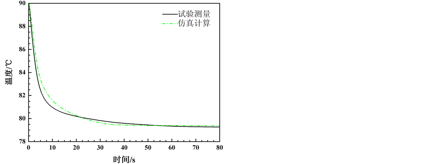
Figure 8. Temperature curves for the initial temperature at 90˚C and superheat at 4˚C
图8. 初始温度90℃,过热度4℃工况下压力曲线

Figure 9. Pressure curves for the initial temperature at 80˚C and superheat at 4˚C
图9. 初始温度80℃,过热度4℃工况下压力曲线

Figure 10. Temperature curves for the initial temperature at 80˚C and superheat at 4˚C
图10. 初始温度80℃,过热度4℃工况下温度曲线
5. 结语
基于汽液两相质量、能量守恒定律,建立了变质量系统热力学模型,借助于Simulink仿真平台,编写仿真计算程序,对船用闪蒸罐闪蒸过程进行计算与分析,仿真结果表明随着闪蒸罐初始水温下降,过热度增加,闪蒸过程中流体温度变化率增大。在不同背压和初始温度工况下仿真得到的压力、温度变化曲线与试验值吻合较好,最大相对偏差在5%左右。因此,非平衡热力学模型在闪蒸罐闪蒸性能仿真计算中的成功应用,可为船用闪蒸罐的热工结构、运行参数的优化设计及船舶蒸汽动力系统设计提供参考。
参考文献 (References)
- [1] Yang, Y.L., Sun, B.Z. and Li, Y.J. (2013) CFD investigation of thermal-hydraulic characteristics for a steam generator with and without tube support plates. Proceedings of the Institution of Mechanical Engineers, Part C: Journal of Mechanical Engineering Science, 31, 358-365.
- [2] Sun, B.Z. and Yang, Y.L. (2013) Numerically investigating the influence of tube support plates on thermal-hydraulic characteristics in a steam generator. Applied Thermal Engineering, 51, 611-622.
- [3] Li, Y.J., Yang, Y.L. and Sun, B.Z. (2013) Numerical investigation of thermal-hydraulic characteristics in a steam generator using a coupled primary and secondary side heat transfer model. Annals of Nuclear Energy, 55, 258-264.
- [4] 倪锦, 顾锦鸿, 沈建 (2012) 船用闪蒸–蒸发海水淡化系统的建模与热力分析. 水处理技术, 1, 47-50.
- [5] 庞虹, 姚征 (2004) 大型海水淡化装置流场数值模拟及其优化. 地址灾害与环境保护, 1, 37-41.
- [6] 齐春华, 范明明, 谢峰, 赵军 (2009) 海水淡化闪蒸罐的闪蒸特性数值模拟及优化设计. 中国给水排水, 12, 87-91.
- [7] 何晨枭, 陈金增, 李光华 (2010) 船用多级闪蒸海水淡化装置的改进. 船海工程, 3, 145-151.
- [8] Pinhasi, G.A., Ullmann, A. and Dayan, A. (2007) 1D plane numerical model for boiling liquid expanding vapor explosion. International Journal of Heat and Mass Transfer, 50, 4780-4795.
- [9] Vladimir, D.S., Blazenka, M. and Sanja, P. (2012) Dynamics of steam accumulation. Applied Thermal Engineering, 37, 73-79.

NOTES
*通讯作者。