Metallurgical Engineering
Vol.
07
No.
01
(
2020
), Article ID:
34104
,
9
pages
10.12677/MEng.2020.71002
Investigation of the Plastic Failure of Purging Plug with Circular Slits in Its Service
Fangguan Tan1, Zhu He1*, Liping Pan1, Yawei Li1, Jun Yang2, Weihu Wu2
1National-Provincial Joint Engineering Research Center of High Temperature Materials and Lining Technology, Wuhan University of Science and Technology, Wuhan Hubei
2Lisheng Co., Ltd., Chengdu Sichuan

Received: Jan. 16th, 2020; accepted: Jan. 29th, 2020; published: Feb. 5th, 2020

ABSTRACT
Purging plug with slits was widely used in secondary metallurgy, and its service life determines the downtime and usage efficiency of the whole ladle. For achieving long service life, the thermomechanical behaviour analysis of purging plug is of great importance. The linear elastic model and the elastic-plastic model are employed to obtain the transient thermo-mechanical stress distribution of the purging plug simplifying the boundary conditions of the service process of the purging plug. By comparing the thermal stress of the two models, it is found that in the process of long-term cyclic service, the purging plug is prone to periodic fatigue. In addition, tensile stress damage of purging plug will happen near r = 0.04 m and y = 0.32 m during the stirring process. Moreover, the damage phenomenon in the actual use that located around the slits is more consistent with the damage prediction under the elastic-plastic model.
Keywords:Elastoplastic Model, Linear Elastic Model, Purging Plug, Failure

圆孔透气塞服役过程的塑性损毁研究
谭方关1,贺铸1*,潘丽萍1,李亚伟1,杨军2,吴畏虎2
1武汉科技大学,高温材料与炉衬技术国家地方联合工程研究中心,湖北 武汉
2成都市力生实业有限责任公司,四川 成都

收稿日期:2020年1月16日;录用日期:2020年1月29日;发布日期:2020年2月5日

摘 要
狭缝式透气塞在钢包精炼中得到广泛的运用,其使用寿命决定了整个冶炼周期的停机时间和冶炼效率。为了延长透气塞的使用寿命,其服役过程中的热机械行为的研究变得尤为重要。在合理的简化透气塞服役过程的边界条件后,分别采用线弹性模型和弹塑性模型得到透气塞服役过程中的瞬态热机械应力分布。通过对比两种模型下的热应力发现,在长期循环服役的过程中,透气塞容易产生周期性疲劳;此外在吹氩期间透气塞内部r = 0.04 m,y = 0.32 m附近容易发生是拉应力损毁;而且,在圆孔透气塞的实际使用过程中的损毁现象与弹塑性模型下损毁预测较为吻合。
关键词 :弹塑性模型,线弹性模型,透气塞,损毁

Copyright © 2020 by author(s) and Hans Publishers Inc.
This work is licensed under the Creative Commons Attribution International License (CC BY).
http://creativecommons.org/licenses/by/4.0/


1. 引言
钢铁工业对于国家来说,犹如骨骼对于人体,而高品质钢占钢铁产量的比重是衡量钢铁工业发展水平的重要指标。目前我国生产高品质钢主要采用炉外精炼技术,而该技术中的钢包底吹氩精炼法采用的关键冶金元件是透气塞。而与钢包里衬不同的是,透气塞在服役过程中不仅与钢渣之间存在传热传质反应和钢水的冲刷作用,还与吹入的高速氩气之间还存在强烈的对流换热,因此透气塞寿命往往比钢包里衬要短,这不仅缩短了钢包的小修周期,从而增加了炼钢成本以及能源消耗。最近,有学者采用圆孔狭缝代替矩形狭缝式透气塞以缓解热应力分布,这不仅延长了透气塞的使用寿命,其冶金性能还有所提高 [1]。如果能了解圆孔透气塞在服役过程中具体损毁原因,就可以基于此原因调整材料配方 [2] 和几何结构优化方法来进一步提高透气塞的热机械性能。
目前,国内外学者往往采用线弹性模型来研究耐火材料的钢水热冲击损毁 [3] [4],然而对于透气塞这类耐火材料来说,不仅要考虑装钢运输时它受到的钢水热冲击,还要考虑吹氩搅拌过程 [5] [6] 中氩气与透气塞之间还存在强烈的热交换现象,因为该传热现象会直接影响透气塞的热变形从而改变其内部的热应力分布。一般来说,透气塞由包含不同颗粒尺寸的板状刚玉、水泥结合剂等等添加剂的刚玉浇注料制作而成 [7] [8]。类似于刚玉浇注料,混凝土也是由不同颗粒尺寸的沙子和水泥组成。然而,在研究混凝土等材料在火灾条件下的损毁时,往往采用Drucker-Prager弹塑性模型来考虑到长期的载荷作用下发生的不可逆塑性形变 [9] [10]。在该模型中,如果材料在屈服应力范围内时,材料表现出弹性行为,超出范围外时则会出现不可逆塑性形变。因此,该模型不仅可以分析冶金用耐火材料在热载荷作用的应力,还可以预测其由不可逆塑性形变造成损毁的位置 [11]。
本文在合理的简化透气塞服役过程的边界条件后,在ANSYS软件中分别采用线弹性模型和弹塑性模型得到透气塞服役过程中的瞬态热机械应力分布后,不仅对比分析了两种模型下的热应力,还预测了透气塞在服役过程中不可逆塑性形变损毁的位置。
2. 数学模型
2.1. 边界条件
为了研究圆孔透气塞在服役过程中的瞬态热机械应力的变化,建立一个符合实际精炼过程的数学模型至关重要。本文在建模过程中考虑了透气塞的预热–装钢–搅拌–浇注等待四个过程,采用热固耦合得到其温度场,然后在分别采用线弹性模型和弹塑性模型对透气塞的热机械应力进行分析。该透气塞的几何模型如图1所示,其材料密度为2.9 g∙cm−3,弹性模量为183 GPa,比热容、热导率、热膨胀系数和泊松比随温度变化等物性参数以及模拟过程的边界条件如文献 [12] 所示,其服役过程的四个阶段持续时间如表1所示,采用修饰的剪切试验法 [11] 得到透气塞用耐火材料的内聚力和摩擦角为80.8 MPa和55.1˚。

Figure 1. Schematic of purging plugs with circular slits
图1. 圆孔透气塞几何模型
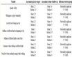
Table 1. Duration and hot face temperatures of the purging plug for each process
表1. 各精炼阶段的持续时间以及工作面的温度
2.2. 热弹性力学方程
透气砖在服役过程中,由于透气砖与外界环境的换热而导致内部温差不均匀,导致透气砖各部位产生不规则的热膨胀,以及透气砖所处位置的约束条件而产生的热应力。本文将透气砖视为弹性介质,其具有弹性热力学基本方程。热应力计算方程包括的平衡方向、几何方程、和物理方程如下所示。
平衡方程:
(1)
几何方程:
(2)
(3)
物理方程:
(4)
(5)
其中 表示为正应力, 为切应力,F为单位体积力,u、v、w为直角坐标位移分量, 为应变, 为泊松比, 为单位长度的扭转角,T为变温。
2.3. 弹塑性模型(Drucker-Prager准则)
如图2所示为Drucker-Prager模型示意图,该模型被广泛的应用于混凝土和岩土领域 [13],因此也同样适用于颗粒材料堆积胶结而成的多相体摩擦型耐火材料。在p (等效应力)-q (静水压力)图中,Drucker-Prager模型可以清楚的判断超出Drucker-Prager屈服线则该点处发生不可逆形变,否则处于弹性区域。

Figure 2. Schematic diagram of Drucker-Prager model
图2. Drucker-Prager模型示意图
(6)
(7)
(8)
(9)
(10)
3. 结果与讨论
如图3所示为透气塞在服役条件下弹塑性模型(a, b, c, d)与线弹性模型(e, f, g, h)的瞬态热机械应力的分布。由图可知,透气塞在吹氩过程中的热机械应力变化最大,对于弹性模型来说,其轴向应力在吹氩阶段不仅拉应力达到最大,而且拉应力区域也明显较多;弹性模型中的拉应力往往集中于在y = 0.32 m

Figure 3. Distribution of the axial stress of purging plug under linear elastic model (a, b, c, d) and elastic- plastic model (e, f, g, h) in service
图3. 服役过程中圆孔透气塞分别在弹塑性模型(a, b, c, d)和塑性模型(e, f, g, h)下的整体轴向应力分布
处的工作面附近。根据耐火材料耐压不耐拉的特点,此时透气最容易发生损毁。而在图3(e, f, g, h)中发现,虽然轴向应力也是在吹氩阶段拉应力达到最大,但是在数值上要明显小于弹性模型中的拉应力,而且拉应力并没有集中于工作面附近;为此,要更一步了解透气塞内部的应力分布,需要对y = 0.32 m截面处的孔周应力进行比较。
如图4所示为吹氩过程中透气塞分别采用弹塑性模型(a, b, c, d)与线弹性模型(e, f, g, h)得到的瞬态热机械应力布。由图可知,透气塞圆孔狭缝周围的存在较大的拉应力;这是由于吹入的氩气与透气塞之间存在较大的对流换热现象导致透气塞圆孔狭缝周围的存在较大的温度变化,而造成热应力的主要原因是温差,故在孔周存在较大的拉应力;而且,在透气塞的中心轴处一直处于压应力状态。因为圆孔能有效的改善应力集中现象,因此在该圆孔的孔周的应力集中现象并不明显;但是,无论在两种模型中,透气塞的外圈狭缝周围存在较大的应力梯度;特别是在弹性模型中,应力梯度变化较大,在透气塞的长期使用过程中,这种应力循环变化势必会导致透气塞周期性疲劳。对比两种模型下的孔周应力发现,采用线弹性模型(e, f, g, h)得到轴向应力的最大值,不仅在数值上要明显的大于采用弹塑性模型得到的最大值;而且在拉应力在分布面积上也要明显的大于弹塑性模型得到的结果。为了更好的反映出透气塞内部的应力变化,选取了如图5所示5个点来对比分析可以造成横向损毁的轴向应力和XZ方向的剪切应力。
如图6所示为透气塞服役过程中A点处的轴向应力。从图可知,在两种模型下,透气塞A点处在服役过程中都处于压应力状态,而且在吹氩期间都存在一个较大的急剧变化;吹氩停止后由于钢水的热传递作用透气塞的温度回升,此时A点处的应力迅速回升;而且在两种模型下轴向应力的差别不大。

Figure 4. Distribution of axial stress around the slits at y = 0.32 m section of purging plug under linear elastic model (a, b, c, d)and elastic-plastic model (e, f, g, h)during stirring process
图4. 吹氩过程中圆孔透气塞y = 0.32 m 截面处分别在弹塑性模型(a, b, c, d)和塑性模型(e, f, g, h)下孔周轴向应力分布

Figure 5. Schematic diagram of different points of purging plug
图5. 透气塞中不同位置点的示意图
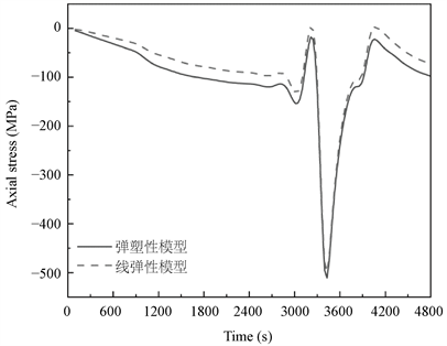
Figure 6. The axial stress of point A of purging plug in service
图6. 透气塞服役过程中A点处的轴向应力
如图7所示为透气塞服役过程中B/C/D点处的轴向应力。由图可知,在两种模型中,透气塞B/C/D点处在吹氩阶段都处于拉应力状态,在吹氩停止后又迅速恢复至压应力状态;如果在透气塞的循环使用过程中,该处最有可能产生周期性疲劳。
如图8所示为透气塞服役过程中E点处的轴向应力。由图可知,在该点处基本处于压应力状态,而且在吹氩3400 s时达到最大值;这是由于在吹氩3400 s时该点处的热对流处于一个平衡状态,此时E点处的温度达到最小值,因此产生较大的温差而引起的热机械应力变化。
如图9所示为透气塞y = 0.32 m截面处Y方向的塑性应变。该图显示,在长期的温度载荷以及固定约束的条件下,透气塞最有可能在吹氩3400 s时发生不可逆塑性应变;综合对比A、B、C、D四点处的轴向应力发现,其值差别并不大,因此发生损毁的位置应该是透气塞的圆孔狭缝的孔周。而且,在实际圆孔透气塞的损毁中,很少出现横断损毁现象,但是部分孔周裂纹较为明显;因此,弹塑性模型能与该孔周裂纹现象较好的吻合。

Figure 7. The axial stress of point B/C/D of purging plug in service
图7. 透气塞服役过程中B/C/D点处的轴向应力

Figure 8. The axial stress of point E of purging plug in service
图8. 透气塞服役过程中E点处的轴向应力

Figure 9. Plastic strain in Y direction at section y = 0.32 m of purging plug
图9. 透气塞y = 0.32 m截面处Y方向的塑性应变
4. 结论
本文分别采用了线弹性模型和弹塑性模型研究了圆孔透气塞在服役过程中的热机械损毁。研究表明,由于吹氩期间氩气与透气塞之间强烈的热交换作用,在吹氩开始和结束后透气塞内部有较大的温差变化,因此导致透气塞内部热机械应力的循环变化;在如此循环服役的过程中,透气塞容易产生周期性疲劳;此外在透气塞内部r = 0.04 m,y = 0.32 m附近的应力在吹氩期间是拉应力状态,因此此处容易发生损毁;而且,通过弹塑性模型发现,最容易发生不可逆塑性变化的位置是圆孔狭缝孔周,这与实际损毁现象能够较好吻合。
基金项目
国家自然科学基金项目[51974211];湖北省中央引导地方科技发展专项[2019ZYYD003] [2019ZYYD076]。
文章引用
谭方关,贺 铸,潘丽萍,李亚伟,杨 军,吴畏虎. 圆孔透气塞服役过程的塑性损毁研究
Investigation of the Plastic Failure of Purging Plug with Circular Slits in Its Service[J]. 冶金工程, 2020, 07(01): 7-15. https://doi.org/10.12677/MEng.2020.71002
参考文献
- 1. 卢寅寅, 谭方关, 贺铸, 等. 底吹钢包用圆孔透气砖冶金效果的水模型[J]. 材料与冶金学报, 2019, 18(1): 41-48.
- 2. Long, B., Xu, G.Y. and Andreas, B. (2017) Microstructure and Physical Properties of Steel-Ladle Purging Plug Refractory Materials. International Journal of Minerals Metallurgy and Materials, 24, 186-193. https://doi.org/10.1007/s12613-017-1394-5
- 3. Damhof, F., Brekelmans, W.A.M. and Geers, M.G.D. (2011) Predictive FEM Simulation of Thermal Shock Damage in the Refractory Lining of Steelmaking Installations. Journal of Materials Processing Technology, 211, 2091-2105. https://doi.org/10.1016/j.jmatprotec.2011.07.005
- 4. Papathanasiou, T.K., Corso, F.D. and Piccolroaz, A. (2015) Thermo-Mechanical Response FEM Simulation of Ceramic Refractories Undergoing Severe Temperature Variations. Journal of the European Ceramic Society, 36, 2329-2340. https://doi.org/10.1016/j.jeurceramsoc.2016.01.022
- 5. Haiyan, T., Xiaochen, G., Guanghui, W., et al. (2016) Effect of Gas Blown Modes on Mixing Phenomena in a Bottom Stirring Ladle with Dual Plugs. ISIJ International, 56, 2161-2170. https://doi.org/10.2355/isijinternational.isijint-2016-360
- 6. Liu, W., Tang, H., Yang, S., et al. (2018) Nu-merical Simulation of Slag Eye Formation and Slag Entrapment in a Bottom-Blown Argon-Stirred Ladle. Metallur-gical and Materials Transactions B, 49, 2681-2691. https://doi.org/10.1007/s11663-018-1308-6
- 7. Long, B., Andreas, B. and Xu, G.Y. (2016) Thermodynamic Evaluation and Properties of Refractory Materials for Steel Ladle Purging Plugs in the System Al2O3-MgO-CaO. Ceramics International, 42, 11930-11940. https://doi.org/10.1016/j.ceramint.2016.04.118
- 8. Long, B., Xu, G.Y., Buhr, A., et al. (2017) Fracture Be-haviour and Microstructure of Refractory Materials for Steel Ladle Purging Plugs in the System Al2O3-MgO-CaO. Ceramics International, 43, 9679-9685. https://doi.org/10.1016/j.ceramint.2017.04.141
- 9. 袁小平, 刘红岩, 王志乔. 基于Drucker-Prager准则的岩石弹塑性损伤本构模型研究[J]. 岩土力学, 2012, 33(4): 148-153.
- 10. 王军祥, 姜谙男. 岩石弹塑性损伤本构模型建立及在隧道工程中的应用[J]. 岩土力学, 2015, 36(4): 1147-1158.
- 11. Jin, S., Gruber, D., Harmuth, H., et al. (2016) Thermomechanical Failure Modeling and Investigation into Lining Optimization for a Ruhrstahl Heraeus Snorkel. Engineering Failure Analysis, 62, 254-262. https://doi.org/10.1016/j.engfailanal.2016.01.014
- 12. Tan, F., He, Z., Jin, S., et al. (2019) Thermomechanical Analysis of Purging Plugs by Applying Fluid-Solid Conjugate Heat Transfer Modeling. Steel Research International, 90, Article ID: 1900213. https://doi.org/10.1002/srin.201900213
- 13. Collins, I.F. (2005) Elastic/Plastic Models for Soils and Sands. International Journal of Mechanical Sciences, 47, 493-508.
NOTES
*通讯作者。