Journal of Oil and Gas Technology
Vol.
45
No.
01
(
2023
), Article ID:
62423
,
12
pages
10.12677/JOGT.2023.451008
中俄东线长江盾构隧道内钢架结构计算
李晓光,崔彦,王婷,张玉
河北工程技术学院土木工程学院,河北 石家庄
收稿日期:2023年1月27日;录用日期:2023年3月3日;发布日期:2023年3月14日

摘要
中俄东线盾构隧道穿越为该线控制性工程,隧道内需设置用于管片运输、管道安装和混凝土运输的钢架结构。为模拟钢架结构的最不利荷载工况,确保钢架结构稳定性和车辆运行安全性,本文利用ANSYS建立了参数化、精细化钢架有限元模型,采用逐步加载法(单车行驶、多车并行)和移动荷载法对钢架结构进行计算分析。结果表明:1) 荷载过钢架时,钢架#4轨道跨中为荷载最不利位置,多车并行对钢架结构受力变形最大值影响不大,可按轨道单车行驶进行计算;2) 钢架结构在荷载作用下受力变形均满足规范要求,但应关注刹车时钢架结构的纵向侧移;3) 钢架结构整体刚度较大,行车速度较低,不会发生共振现象,车辆冲击效应不显著。
关键词
中俄东线长江盾构隧道,钢架结构,逐步加载法,移动荷载法,有限元

Calculation of Steel Frame Structure in Yangtze River Shield Tunnel of China Russia East Line
Xiaoguang Li, Yan Cui, Ting Wang, Yu Zhang
School of Civil Engineering, Hebei Institute of Engineering and Technology, Shijiazhuang Hebei
Received: Jan. 27th, 2023; accepted: Mar. 3rd, 2023; published: Mar. 14th, 2023

ABSTRACT
The shield tunnel crossing of China Russia east line is a control project of the line, and the steel frame structure used for segment transportation, pipeline installation and concrete transportation should be set in the tunnel. In order to simulate the most unfavorable load conditions of steel frame structure and ensure the stability of steel frame structure and the safety of vehicle operation, a parameterized and refined finite element model of steel frame is established by using ANSYS, and the calculation and analysis of steel frame structure are carried out by using step-by-step loading method (single vehicle driving, multi vehicle parallel) and moving load method. The results show that: 1) When the load passes through the steel frame, the middle of the steel frame #4 track span is the most unfavorable position for the load, and the multi vehicle parallel has little effect on the maximum stress and deformation of the steel frame structure, which can be calculated as a single vehicle running on the track; 2) The stress and deformation of the steel frame structure under the action of load meet the requirements of the code, but the longitudinal lateral displacement of the steel frame structure during braking should be paid attention to; 3) The overall stiffness of the steel frame structure is large, the driving speed is low, the resonance phenomenon will not occur, and the vehicle impact effect is not significant.
Keywords:China Russia East Line Yangtze River Shield Tunnel, Steel Frame Structure, Step by Step Loading Method, Moving Load Method, Finite Element Method

Copyright © 2023 by author(s) and Hans Publishers Inc.
This work is licensed under the Creative Commons Attribution International License (CC BY 4.0).
http://creativecommons.org/licenses/by/4.0/


1. 前言
中俄东线(永清–上海)管道全长1509 km。南通–甪直段为新建管道,全长约178 km,管径1422 mm。中俄东线天然气管道工程长江盾构隧道在穿越长江时采用盾构隧道穿越方案,是中俄东线的控制性工程。根据管道安装需要,隧道内设置钢结构支架,管道支承于钢结构支架上。钢结构支架主要用于隧道施工时管片运输,管道安装时支承管道重量,隧道内泡沫混凝土浇筑时承担混凝土运输罐车重量。为保证钢架结构稳定性和车辆运行安全性,分析钢架结构在竖向移动荷载和制动荷载下的变形受力情况。本文采用逐步加载法和移动荷载法对钢架结构进行计算分析。
2. 荷载计算
本文主要考虑运输小车运输时的竖向荷载和刹车时的制动荷载。其中竖向荷载主要为盾构拖车荷载、盾构施工运输车荷载和运管小车荷载。
竖向荷载:盾构拖车荷载、盾构施工运输车荷载和运管小车荷载如图1~3所示。
制动荷载:将制动荷载施加到轨道顶层钢架单元,制动荷载采用均布荷载进行施加,荷载范围为轮间距2.67 m,制动力率取0.1。

Figure 1. Shield trailer load
图1. 盾构拖车荷载

Figure 2. Shield construction truck load
图2. 盾构施工运输车荷载

Figure 3. Load of pipe transport trolley
图3. 运管小车荷载
3. 逐步荷载法过钢架
3.1. 钢架有限元模型
采用有限元软件ANSYS建立精细化、参数化钢架有限元模型。其中钢架结构构件主要包括:H型钢和轨道,其有限元模型如图4所示。ANSYS有限元建模时,H型钢和轨道均采用梁单元进行模拟,轨道与钢架间采用弹簧单元连接。钢架与隧道壁接触点处均采用全约束。各构件单元使用详情如表1所示。

Figure 4. Finite element model of steel frame
图4. 钢架有限元模型
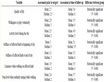
Table 1. Description of element types of finite element model of steel frame
表1. 钢架有限元模型单元类型说明
3.1.1. 模型构件建模参数
钢架结构采用HW300 × 300 × 10 × 15、HW150 × 150 × 7 × 10、HW100 × 100 × 6 × 8和HM300 × 200 × 8 × 12四种H型钢。主要构件建模参数如表2所示。
Table 2. Model component modeling parameter information table
表2. 模型构件建模参数信息表
3.1.2. 自重变形
图5所示为钢架模型在自重作用下的垂向变形图,其中最大值出现在轨道跨中位置,最大变形为0.058 mm。

Figure 5. Vertical deformation diagram of model under dead weight
图5. 自重作用下模型垂向变形图
3.2. 逐步加载法程序
采用自编逐步加载法程序对钢架结构进行分析,逐步加载法程序流程图如图6所示。计算过程中荷载大小始终恒定,其作用位置为每个轨道单元节点,当某一位置单元节点结束时,则会“跳跃”至下一单元节点,再持续一个荷载步。从而实现荷载的逐步施加。加载模式如图7所示。

Figure 6. Procedure flow chart of step-by-step loading method
图6. 逐步加载法程序流程图

Figure 7. Schematic diagram of loading mode of step-by-step loading method
图7. 逐步加载法加载模式示意图
3.3. 计算结果
为分析单车行驶与多车并行对钢架结构变形和受力。图8给出了单车行驶和多车行驶下随车辆位置变化的顶层钢架跨中单元竖向位移和弯矩对比结果。从中可以看出:单车行驶与多车并行时,轨道顶层钢架跨中处的竖向位移与弯矩相差很小,可忽略不计。
 (a)
(a)
 (b)
(b)
Figure 8. Comparison between single-vehicle driving and multi-vehicle driving results. (a) Vertical displacement diagram of mid-span unit; (b) Bending moment diagram of mid-span unit
图8. 单车行驶、多车行驶结果对比图。(a) 跨中单元竖向位移图;(b) 跨中单元弯矩图
100 kN轮载单车在钢架结构轨道行驶时,图9给出了随车辆位置变化的顶层钢架各单元竖向位移、弯矩和轴力。
 (a)
(a)
 (b)
(b)
 (c)
(c)
Figure 9. Stress diagram of deformation of each unit of top steel frame during single vehicle driving. (a) Vertical displacement of each unit; (b) Bending moment of each unit; (c) Axial force of each unit
图9. 单车行驶时顶层钢架各单元变形受力图。(a) 各单元竖向位移;(b) 各单元弯矩;(c) 各单元轴力
图10给出了制动荷载下,轨道顶层钢架不同位置处的纵向位移。

Figure 10. Longitudinal displacement of top steel frame at different positions
图10. 顶层钢架不同位置纵向位移
依据上述相同的计算方法,求得#2 (#3)轨道梁1/4跨竖向位移、#2 (#3)轨道柱顶侧位移。与规范限值对比情况如表3所示。
Table 3. Displacement comparison of steel frame structure
表3. 钢架结构位移对比
3.4. 小结
通过对逐步加载法过钢架变形和受力分析,可以得到以下结论:
1) 单车行驶、多车行驶时,钢架最大竖向位移、最大弯矩均出现在轨道顶层钢架跨中处。
2) 单车行驶与多车并行时,轨道顶层钢架跨中处的竖向位移与弯矩相差很小,可忽略不计。多车并行对钢架结构受力变形最大值影响不大,可按轨道单车行驶进行计算。
3) 通过计算,钢架在竖向荷载和制动荷载作用下,竖向和纵向变形均满足规范要求。
4. 移动荷载法过钢架
交通运输领域中,存在多种作用有移动荷载的结构,如桥梁、导轨、索道、钢轨、轨枕、道路等。与其他动力问题不同,移动荷载的位置随时间而变化,这使得该问题成为结构动力学中的一个特殊课题,受到了广泛的关注 [1] 。目前,针对移动荷载问题,主要有2种求解方法:解析方法和有限元方法。已有学者通过Winkler假定对恒速移动荷载作用下的梁板动力响应进行了研究,同时详细探究了剪力、转角、轴力和粘滞阻尼受临界速度的影响 [2] 。
4.1. 钢架结构动力特性
对钢架结构进行了动力特性分析,表4列出了钢架前9阶振型频率,图11所示为钢架前4阶振型图。
Table 4. Natural vibration frequency and vibration mode of steel frame
表4. 钢架自振频率及振型
 (a)
(a)
 (b)
(b)
 (c)
(c)
 (d)
(d)
Figure 11. The first four vibration modes of steel frame. (a) First mode; (b) Second-order vibration mode; (c) Third-order mode; (d) Fourth order vibration mode
图11. 钢架前四阶振型图。(a) 一阶振型;(b) 二阶振型;(c) 三阶振型;(d) 四阶振型
1) 该结构的基频为32.8 Hz,说明该结构整体刚度较大。
2) 该结构从第2阶到第9阶相邻频率接近,说明该钢架模态十分密集。前8阶主要为横弯模态,第9节为竖弯模态,说明钢架竖向整体刚度较大,横向刚度较竖向刚度偏小。特别应注意(刹车时)轨道纵向侧移的发生。
单榀钢架跨度为3 m,车速为5 m/s时,对应的列车荷载激励频率为1.87 Hz (根据公式(1)计算,其中v代表车速,Lv代表车长)。远小于结构自振频率,故运行列车与单榀钢架结构不会发生共振现象。
(1)
4.2. 移动荷载法程序
对于移动荷载问题的求解,采用了较为常见的直接积分方法。计算过程中荷载大小始终恒定,其作用位置在每个时间步内保持不变,当某一时间步结束时,则会“跳跃”至另一个位置,再持续一个时间步。从而,将荷载的连续移动过程,离散为一系列作用于不同位置的荷载脉冲的叠加,如图12所示。
图13中所示荷载在每一时间步均恰好作用于节点之上,实际上,但是当步长取值发生变化时,荷载作用位置则为两个节点之间,此时,需要根据插值函数对荷载进行分配,从而将其等效于两侧节点上。本文中采用Hermit三次插值函数实现荷载分配,如图13所示。

Figure 12. Equivalent schematic diagram of moving load
图12. 移动荷载等效示意图

Figure 13. Schematic diagram of load distribution
图13. 荷载分配示意图
当荷载作用于第m个单元时,其两端节点分别为n和n + 1,则该单元所受外荷载可表示为:
(2)
式中, 为钢轨单元的形函数,可表示为
(3)
其中, , , , 为轨道单元的形函数
(4)
(5)
(6)
(7)
其中,x表示轮对在轨道单元中距单元左端的距离;l表示梁单元的长度,见图13。
对梁体动力响应进行求解时采用直接积分法(Newmark-β法),详见文献 [3] 。
4.3. 计算结果
工况信息:车速采用设计车速5 m/s,计算时积分步长采用0.01 s。
100 kN轮载单车在钢架结构轨道行驶时,图14给出了随车辆位置变化的顶层钢架跨中节点的竖向位移与加速度。
 (a)
(a)
 (b)
(b)
Figure 14. Dynamic response of mid-span node. (a) Vertical displacement of mid-span node; (b) Vertical acceleration of mid-span node
图14. 跨中节点动力响应。(a) 跨中节点竖向位移;(b) 跨中节点竖向加速度
图15给出了相同工况下逐步加载法和移动荷载法钢架竖向位移的结果对比情况,从图15中可以看出,竖向位移最大值相差很小,动力冲击效应不太显著。

Figure 15. Comparison of vertical displacement results of steel frame
图15. 钢架竖向位移结果对比
4.4. 车速对钢架结构的影响
为分析车速对钢架结构的影响,采用设计车速5 m/s的2倍、3倍车速作为补充工况进行对比。不同车速轨道节点动力响应如图16所示。
 (a)
(a)
 (b)
(b)
Figure 16. Dynamic response of mid-span nodes at different speeds. (a) Vertical displacement of mid-span node; (b) Vertical acceleration of mid-span node
图16. 不同车速跨中节点动力响应。(a) 跨中节点竖向位移;(b) 跨中节点竖向加速度
4.5. 小结
1) 应关注刹车时钢架轨道纵向侧移。运行列车与单榀钢架结构不会发生共振现象。
2) 由于钢架结构整体刚度较大,车辆行车速度较低,故车辆的冲击效应不显著。
3) 车速对轨道钢架跨中处的竖向位移影响不大,该处加速度峰值随车速增大有所提升。
5. 结论
1) 荷载(单车行驶、多车并行)过钢架时,变形和受力最不利点为轨道钢架跨中处。多车并行对钢架结构受力变形最大值影响不大,可按轨道单车行驶进行计算。
2) 逐步加载时钢架各轨道钢架单元的竖向位移和纵向侧移均满足规范要求。
3) 应关注刹车时钢架结构纵向侧移的发生,由于钢架结构整体刚度较大,车辆行车速度较低,故车辆的冲击效应不显著。
基金项目
2019-GK-特长距离高水压盾构隧道穿越关键技术研究。
文章引用
李晓光,崔 彦,王 婷,张 玉. 中俄东线长江盾构隧道内钢架结构计算
Calculation of Steel Frame Structure in Yangtze River Shield Tunnel of China Russia East Line[J]. 石油天然气学报, 2023, 45(01): 56-67. https://doi.org/10.12677/JOGT.2023.451008
参考文献
- 1. Suzuki, S.I. (1977) Dynamic Behaviour of a Finite Beam Subjected to Travelling Loads with Acceleration. Journal of Sound and Vibration, 55, 65-70. https://doi.org/10.1016/0022-460X(77)90583-1
- 2. Frýba, L. and Steele, C.R. (1976) Vibration of Solids and Structures under Moving Loads. Journal of Applied Mechanics, 43, 524.
- 3. Kraft, R. and Peng Jin, J. (2006) Structural Dynamics. 2nd Edition, Higher Education Press, Beijing.