Dynamical Systems and Control
Vol.
12
No.
02
(
2023
), Article ID:
64939
,
13
pages
10.12677/DSC.2023.122013
基于随机路面识别的半主动悬架控制策略研究
姜清伟1,崔恩有2,张新峰1,刘伟1
1中国汽车技术研究中心有限公司,天津
2中汽研汽车零部件检验中心(宁波)有限公司,浙江 宁波
收稿日期:2023年3月28日;录用日期:2023年4月22日;发布日期:2023年4月29日

摘要
为了解决半主动悬架系统存在的时滞问题,本文提出一种基于随机路面识别和半主动悬架控制技术相结合的智能悬架控制方法。目前量产车型配置的半主动悬架系统一般有三种模式:舒适、标准及运动。每种模式是由驾驶员根据不同路况进行选择,导致了半主动悬架系统使用的局限性,不能对工况进行自适应控制。本文通过构建卷积神经网络对随机路面进行分类识别,将识别的路面不平度信息提前反馈给半主动悬架控制器,可以满足不同路况下的自适应悬架控制,并通过整车道路实验验证了所提算法的有效性。
关键词
控制策略,半主动悬架,随机路面

Research on Control Strategy of Semi-Active Suspension Based on Random Road Surface Identification
Qingwei Jiang1, Enyou Cui2, Xinfeng Zhang1, Wei Liu1
1China Automotive Technology and Research Center Co., Ltd., Tianjin
2CATARC Automotive Component Test Center (Ningbo) Co., Ltd., Ningbo Zhejiang
Received: Mar. 28th, 2023; accepted: Apr. 22nd, 2023; published: Apr. 29th, 2023

ABSTRACT
To solve the time-delay problem of semi-active suspension system, an intelligent suspension control method based on the combination of random road surface identification and semi-active suspension control technology is proposed. At present, there are three modes of semi-active suspension system configured for mass production vehicles: comfort, standard and sport. Each mode is selected by the driver according to different road conditions, which leads to the limitation of semi- active suspension system, and cannot adaptively control the working conditions. In this paper, a convolutional neural network is constructed to classify and identify random road surfaces. The identified road roughness information is fed back to the semi-active suspension controller in advance, which can meet the adaptive suspension control under different road conditions. The effectiveness of the proposed algorithm is verified by vehicle road experiments.
Keywords:Control Strategy, Semi-Active Suspension, Random Pavement

Copyright © 2023 by author(s) and Hans Publishers Inc.
This work is licensed under the Creative Commons Attribution International License (CC BY 4.0).
http://creativecommons.org/licenses/by/4.0/


1. 引言
随着电动化、智能化和网络化成为汽车行业的发展趋势,智能汽车将成为全球汽车工程领域的研究重点,并成为汽车行业增长的新动力。由于不可调节的刚度和阻尼,被动悬架已无法满足智能汽车的驾驶需求。由于刚度或阻尼可调,半主动悬架系统可以更好地解决智能车辆的操纵稳定性和平顺性匹配问题,已成为悬架系统的主要发展趋势。
目前,用于半主动悬架系统研究和开发的控制算法主要包括:反推控制 [1] 、滑模控制 [2] 、模糊控制 [3] 、H∞控制 [4] 、自适应控制 [5] 、模型预测控制 [6] [7] 、神经网络控制 [8] [9] 等。就算法的可实现性和工程应用而言,天棚控制是应用最广泛的 [10] - [16] 。但是这些控制方法要求传感器收集输入信号以控制变量,从而导致半主动悬架系统的输出响应延迟并降低控制效果。
近年来,为了解决半主动悬架控制器的时间延迟问题,研究人员在主动悬架控制策略的制定中添加了前方道路信息,从而开发了预瞄控制等智能控制方法 [17] [18] [19] [20] [21] 。但这些控制方法只是基于固定工况实现,不能根据路况进行自适应控制,这导致了半主动悬架系统的局限性。本文提出了一种基于随机路面识别和半主动悬架控制技术相结合的智能悬架控制方法。该方法不仅可以解决半主动悬架系统的响应延迟问题,而且可以对控制算法进行微调。天棚加速度仅由两级开关控制,并在通过视觉感知提前识别路面水平的基础上引入控制算子,可在两级的基础上实现三级控制,进一步优化半主动悬架系统的控制效果。
2. 整车动力学模型
整车七自由度模型包含车辆质心俯仰、侧倾和横摆以及四个车轮的轮跳运动,可以忽略车轮转动等影响因素较小的自由度,通过俯仰及侧倾运动对车辆操纵稳定性进行研究,通过轮跳运动对车辆平顺性进行研究,满足对车辆操纵稳定性及平顺性的控制策略研究。将整车模型自由度简化后,一方面可以减少计算时间,另一方面避免自由度过多模型解耦困难,造成控制算法不收敛。本节建立的七自由度动力学模型如图1所示,将悬架系统进行线性化,假设车辆俯仰及侧倾较小,通过数学模型计算得出车辆状态变量方程。

Figure 1. Vehicle dynamics model
图1. 整车动力学模型
利用牛顿第二定律,簧载质量的轮跳运动为
(1)
簧载质量的俯仰运动为
(2)
簧载质量的侧倾运动为
(3)
左前轮的垂向运动方程为
(4)
右前轮的垂向运动方程为
(5)
左后轮的垂向运动方程为
(6)
右后轮的垂向运动方程为
(7)
通过选择以下的状态变量、扰动量及控制量
(8)
(9)
(10)
半主动悬架系统的状态方程为
(11)
3. 控制算法设计
3.1. 传统天棚阻尼控制算法
天棚阻尼控制的理想模型是在车身和假想惯性参考系“天钩”之间安装一个用于能量耗散的阻尼器,当阻尼系数达到一定值时,该方法可以获得相应的车身减振效果。在实际应用中,不可能在簧载质量和惯性基准之间安装真正的阻尼器,因此将假设的阻尼器转化为改进的天钩阻尼控制模型。以左前悬架为例,skyhook阻尼控制是一种通过两态阻尼实现的开关控制模式,其控制算法可以表示为:
(12)
天棚阻尼控制的机理是判断簧上质量和簧下质量的相对运动速度方向,以切换阻尼系数,但由于瞬态道路的冲击时间短,控制系统的响应不及时,导致控制效果不佳。如果与车辆预瞄信息相结合,将进一步提高乘坐舒适性。
3.2. 混合自适应预瞄控制算法
首先搭建带有预瞄功能的整车七自由度模型,如图1所示,该模型主要用于验证车辆的垂向性能。假定悬架系统模型为线性系统,侧倾角和俯仰角较小,从数学模型中提取半主动悬架系统状态变量。模型受限的条件是不包括汽车的转向系统,设定速度是固定值但可以是任意的。
将典型瞬态道路纵向长度定义为L0。在不考虑轮胎弹性的情况下,车辆通过典型道路的时间为
(13)
式中, 是车速方向与水平方向的夹角。 表示控制系统的时滞。当 时,控制系统将响应一定程度的延迟,而当 时,控制系统将无法正常工作,甚至会影响乘坐舒适性。
在图1中,L是预瞄距离,可以通过深度学习的目标检测方法获取。预瞄时间τ表示为
(14)
当 时,自适应悬架控制的时间延迟将被预瞄控制完全抵消。以左前悬架为例,混合自适应悬架预瞄控制的动力学模型公式为
(15)
式(15)用状态空间可表示为
(16)
通过拉普拉斯变换,将预瞄点道路输入 与当前道路输入 之间的传递函数表示为
(17)
采用二阶Pade近似公式将式(17)转化为状态空间形式,其方程表达式为
(18)
这里
(19)
预瞄控制系统状态空间方程的形式可表示为
(20)
这里
(21)
已知的预瞄控制变量主要有:预瞄时间τ、当前时刻的道路输入q(t)、预瞄点q (t + τ)的道路输入及道路类型。自适应悬架控制对各时刻系统的时间和状态不敏感,仅对当前路面不平度的变化程度有响应,根据其控制原理只有“开”和“关”两个维度,只能对半主动悬架系统进行较为宽泛的控制,不能对车辆舒适性的控制效果进行精细化调校。因此,如果将道路强度定义为“不严重”、“相对严重”和“严重”三种类型,通过深度学习提前识别路面类型,那么混合自适应悬架预瞄控制可根据道路类型的变化进行精细化调校,对车辆舒适性实现更好的控制效果。输出阻尼与道路类型变化的关系为
(22)
式中,把沥青路、灰尘路及混凝土补丁路等归为“不严重”路面等级,把井盖路、锯齿路及比利时路等归为“相对严重”路面等级,把坑洼路、鹅卵石路及减速带路等归为“严重”路面等级,δ1通过实车路试标定获取。
4. 基于卷积神经网络的随机道路识别
4.1. VGG16网络
VGGNet网络使用33的卷积核的新型算子,通过不断的堆叠3 × 3卷积核以及使用2 × 2结构的最大池化层,建立了16层至19层较深的网络结构,提高了分类精度,但增加了处理时间,该网络具有结构简单、泛化性较好的优点,比较适用于图像特征提取及分类。本文首先选用的是具有16层深度的VGG16网络进行路面识别,其结构如图2所示。
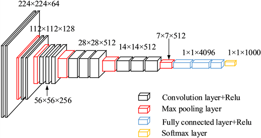
Figure 2. VGG16 network architecture diagram
图2. VGG16网络架构图
4.2. ResNet网络
ResNet网络在2015年ILSVRC分类比赛项目中取得了第一名的好成绩,其采用残差学习理论,使神经网络的卷积层扩展更深形成较深的网络结构,提升了目标分类的精度。本文选用的是具有50层深度的ResNet50网络模型对路面进行分类识别。残差网络可以直接将前一层的输出结果映射到后一层,并与后一层网络输出结果的差值作为新的学习目标,如图3所示,此种网络结构不再是完整的输出训练,而是采用残差方式保留了信息的完整性。
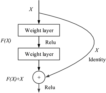
Figure 3. ResNet residual learning module
图3. ResNet残差学习模块
4.3. 数据集选择
本文通过视频采集方式获取15种典型道路数据集,将摄像头以一定角度固定在车辆易于安装的位置(如内后视镜或者前保险杠),采集分辨率为720 × 480。为提高数据质量以及模型的泛化能力,采集不同角度不同种类路面视频,以5帧/秒截取图片,提取不同种类路面的数据集,每种类型提取500幅图像。由于原始数据量较小,为了更好的训练模型,需要增加数据集。通过对图像进行180度旋转、镜像、加噪、调整亮度、高斯滤波等处理,数据集可扩展到原始数据的10倍。
4.4. 实验结果分析
使用两种深度学习的网络模型对15种随机路面分类结果进行统计,得出的结果分别如图4和图5所示。测试中选用了在两种不同训练次数下的测试结果做横向对比,从分类结果可以看出,VGG16网络模型在一些特征不明显的目标分类效果并不良好,在使用ResNet网络模型进行训练识别后分类效果有显著提升。从量化结果可以看出ResNet模型的分类结果明显优于VGG16模型,主要是由于其采用残差学习理论,使神经网络的卷积层扩展更深形成较深的网络结构,保留了路面特征信息的完整性,大幅度提升了目标分类的精度。
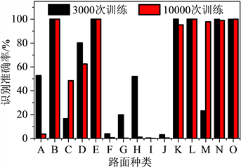
Figure 4. VGG16 classification results
图4. VGG16分类结果
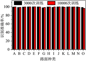
Figure 5. ResNet classification results
图5. ResNet分类结果
5. 半主动悬架系统控制流程
图6为混合自适应悬架预瞄控制的结构框图。当前路面类型作为输入激励,车轮及悬架系统S(s)垂向速度发生改变,此时车轮输出的垂向位移为z1,速度为v1,由于减振器等作用使车身系统B(s)的垂向加速度a2发生变化,此时车身处输出的垂向速度为v2,车身与车轮的相对运动速度关系输入至自适应悬架控制系统Sh(s),系统根据判据决定当前输出的阻尼值C2是否发生改变,使得悬架作用力u进行调整,从而作用于车身,自适应悬架控制系统Sh(s)再根据当前反馈信息作用于下一步输出。加入预瞄控制Pre(s)之后,前方路面类型被提前一个时间量τ获取,此时判断该是何种类型路面,根据路面类型进行设定的路面等级,预瞄系统会延迟τ时刻,输出一个新的阻尼值C1,与自适应控制系统输出的阻尼值共同控制减振器,从而优化控制量输出目标。
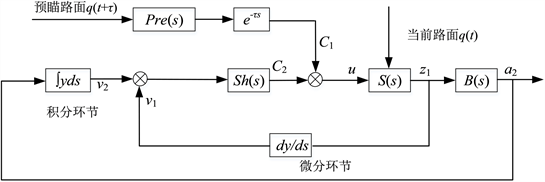
Figure 6. Structure diagram of hybrid adaptive suspension preview control system
图6. 混合自适应悬架预瞄控制系统结构图
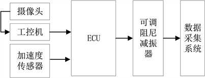
Figure 7. System control flow chart
图7. 系统控制流程图
根据上述原理设计半主动悬架系统控制流程,并通过外置电磁阀可调阻尼减振器验证混合自适应悬架预瞄控制方法。半主动悬架系统控制流程如图7所示。该系统由摄像头、工控机、5个加速度传感器、ECU、4个电磁阀和一套Head数据采集系统组成。摄像头为CCD型,分辨率为720 × 480;工控机由NVIDIA GeForce GTX 1060 GPU、8GB RAM、Intel I5 8400 CPU等组成;加速度传感器的类型为MEMS,量程为±1.6 g;ECU是基于英飞凌嵌入式系统进行开发的,包括6通道ADC信号、2通道CAN信号和4通道PWM信号;可调阻尼减振器为外置电磁阀型,通过电流控制改变电磁阀的开度大小,从而控制和调节阻尼力;数据采集系统是16通道的数采设备,用来采集质心加速度和簧载加速度数据,分析控制策略的优化效果。
所用整车模型参数如下:ms = 1775 kg,mf = 1084 kg,mr = 691 kg,mufl = mufr = 52.2 kg,murl = murr = 34.6 kg,Ix = 830 kg m2,Iy = 3684 kg m2,ksfl = ksfr=31000 N/m,ksrl = ksrr = 65000N/m,ktfl = ktfr = ktrl = ktrr = 220,000 N/m,lf = 1.05 m,lr = 1.7 m,wf = wr = 1.615 m。
6. 整车道路实验
良好的车辆操纵稳定性和平顺性是乘客对汽车性能评价的重要指标,也是保证乘客满意的前提。特别是随着无人驾驶智能车的深入发展,当乘客彻底无需再进行频繁的驾驶操作,将会对车辆的舒适性更加关注。目前,半主动悬架技术已经成为悬架系统发展的一个重要趋势,研究并开发半主动悬架系统已经成为国内外学者研究的一个焦点。外置电磁阀可调阻尼减振器作为一种阻尼力连续可调的、响应时间较快的悬架系统减振元件,相对于传统被动减振器有更好的减振效果,但是在接收到控制信号并完成执行动作时会有一定的响应延迟。而采用了基于深度学习的路面识别技术可为半主动悬架控制系统提供预瞄来消除整个控制系统的滞后。本实验主要研究对比所提控制算法与外置电磁阀可调阻尼减振器在不同路面、不同车速下车内各测点的振动加速度相对于传统减振器下降的幅值,验证混合自适应悬架预瞄控制在整车平顺性方面相对普通减振器的优越性。
为了方便分析不同半主动悬架控制策略与被动悬架之间的性能对比,将被动悬架简写为PS (Passive Suspension),自适应悬架控制简写为ADS (Adaptive Damping System),混合自适应悬架预瞄控制简写为M-ADS (Mixed Adaptive Damping System)。另外,天棚轴距预瞄控制,简写为SWPC (Skyhook Wheelbase Preview Control),作为传统时滞补偿控制算法之一,通过加速度信号感知路面激励大小,通过车速与轴距计算出预瞄时间,为后悬架提供预瞄控制。本文选择将SWPC与M-ADS进行对比,以体现出本文所提算法解决时滞的优势。
实验道路为直线路段,路面有粗糙沥青路和比利时路,如图8和图9所示。图10~13分别为M-ADS、SWPC、ADS和PS在40 km/h速度下通过粗糙沥青路和比利时路的时域与频域对比曲线。由于车辆匀速下通过随机路面时车身姿态变化较小,半主动悬架系统此时主要是对车辆垂向加速度影响较大,而对于车辆纵向加速度及侧向加速度影响较小,所以选取驾驶员座椅Z向振动和地板Z向振动作为对比参数。

Figure 8. Rough asphalt road
图8. 粗糙沥青路

Figure 9. Belgium road
图9. 比利时路
通过时域数据可知,与SWPC、ADS和PS相比,可以发现M-ADS在驾驶员座椅Z向振动和驾驶员地板Z向振动的加速度幅值有所降低。通过频域数据可以发现,在粗糙沥青路下,与被动悬架相比,不同控制策略主要是在3~10 Hz频段降低驾驶员座椅Z向振动和在4~30 Hz频段降低驾驶员地板Z向的中低频振动,比利时路面下主要是在4~25 Hz频段降低驾驶员座椅Z向振动以及在20~50 Hz频带降低驾驶员地板Z向振动。
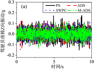
Figure 10. Z-direction vibration data comparison of driver seat on 60 km/h rough asphalt road: (a) Time domain, (b) Frequency domain
图10. 粗糙沥青路60 km/h驾驶员座椅Z向振动数据对比:(a) 时域;(b) 频域

Figure 11. Z-direction vibration data of driver floor of 60 km/h rough asphalt road: (a) Time domain, (b) Frequency domain
图11. 粗糙沥青路60 km/h驾驶员地板Z向振动数据:(a) 时域;(b) 频域
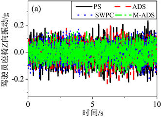
Figure 12. Z-direction vibration data of driver seat at 40 km/h Belgium road: (a) Time domain, (b) Frequency domain
图12. 比利时路40 km/h驾驶员座椅Z向振动数据:(a) 时域;(b) 频域

Figure 13. Z-direction vibration data of driver floor of 40 km/h Belgium road: (a) Time domain, (b) Frequency domain
图13. 比利时路40 km/h驾驶员地板Z向振动数据:(a) 时域;(b) 频域
表1列出了三种控制策略与PS通过不同路面不同车速时的道路测试结果,表中数据为同一工况三组数据取平均值得出的结果。通过对驾驶员座椅Z向加速度和驾驶员地板Z向加速度频域RMS值的比较,也验证了M-ADS控制效果优于SWPC、ADS和PS。
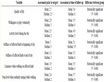
Table 1. Test results under different control algorithms on random roads
表1. 随机路面下不同控制算法的实验结果
7. 结论
本文设计了一种基于随机路面识别和半主动悬架控制技术相结合的智能悬架控制方法,解决了半主动悬架系统的响应延迟问题,得出的结论主要有:
1) 通过构建基于深度学习的VGG16和ResNet网络模型对随机路面进行识别并进行对比,ResNet模型的分类结果明显优于VGG16模型,主要是由于其采用残差学习理论,使神经网络的卷积层扩展更深形成较深的网络结构,保留了路面特征信息的完整性,大幅度提升了目标分类的精度。
2) 本文构建的混合自适应阻尼控制算法实现了对车辆的平顺性进行优化,与PS、ADS和SWPC相比,通过在不同速度和不同道路下的实车试验,通过驾驶员座椅和地板的Z方向振动等客观测试数据,验证了该算法的有效性。
文章引用
姜清伟,崔恩有,张新峰,刘 伟. 基于随机路面识别的半主动悬架控制策略研究
Research on Control Strategy of Semi-Active Suspension Based on Random Road Surface Identification[J]. 动力系统与控制, 2023, 12(02): 120-132. https://doi.org/10.12677/DSC.2023.122013
参考文献
- 1. Pang, H., Zhang, X. and Yang, J.J. (2019) Adaptive Backstepping-Based Control Design for Uncertain Nonlinear Active Suspension System with Input Delay. International Journal of Robust and Nonlinear Control, 29, 5781-5800.
https://doi.org/10.1002/rnc.4695 - 2. Zhou, C., Liu, X.H. and Chen, W. (2018) Optimal Sliding Mode Control for an Active Suspension System Based on a Genetic Algorithm. Algorithms, 11, 205-221.
https://doi.org/10.3390/a11120205 - 3. Kumar, V., Rana, K.P.S., Kumar, J. and Mishra, P. (2018) Self-Tuned Robust Fractional Order Fuzzy PID Controller for Uncertain and Nonlinear Active Suspension System. Neural Computing and Applications, 30, 1827-1843.
https://doi.org/10.1007/s00521-016-2774-x - 4. Yang, M.L., Peng, C., Li, G.L., Wang, Y.L. and Ma, S.D. (2019) Event-Triggered H∞ Control for Active Semi-Vehicle Suspension System with Communication Constraints. Information Sciences, 486, 101-113.
https://doi.org/10.1016/j.ins.2019.02.047 - 5. Kararsiz, G., Paksoy, M. and Metin, M. (2020) An Adaptive Control Approach for Semi-Active Suspension Systems under Unknown Road Disturbance Input Using Hardware-in-the-Loop Simulation. Transactions of the Institute of Measurement and Control, 43, 995-1008.
https://doi.org/10.1177/0142331219895935 - 6. Wang, Z.F., Xu, S.J., Li, F., et al. (2020) Integrated Model Predictive Control and Adaptive Unscented Kalman Filter for Semi-Active Suspension System Based on Road Classification. SAE Technical Paper 2020-01-0999.
https://doi.org/10.4271/2020-01-0999 - 7. Kaldas, M., Soliman, A., Abdallah, S. and Amien, F. (2020) Robustness Analysis of the Model Reference Control for Active Suspension System. SAE International Journal of Vehicle Dynamics, Stability, and NVH, 4, 165-177.
https://doi.org/10.4271/10-04-02-0012 - 8. Qin, Y.C., Xiang, C.L. and Wang, Z.F. (2018) Road Excitation Classification for Semi-Active Suspension System Based on System Response. Journal of Vibration and Control, 24, 2732-2748.
https://doi.org/10.1177/1077546317693432 - 9. Konoiko, A., Kadhem, A. and Saiful, I. (2019) Deep Learning Framework for Controlling an Active Suspension System. Journal of Vibration and Control, 25, 2316-2329.
https://doi.org/10.1177/1077546319853070 - 10. Karnopp, D., Crosby, M.J. and Harwood, R.A. (1974) Vibration Control Using Semi-Active Force Generators. ASME Journal of Engineering for Industry, 96, 619-626.
https://doi.org/10.1115/1.3438373 - 11. Sammier, D., Sename, O. and Dugard, L. (2003) Skyhook and H∞ Control of Semi-Active Suspensions: Some Practical Aspects. Vehicle System Dynamics, 39, 279-308.
https://doi.org/10.1076/vesd.39.4.279.14149 - 12. Liu, C.N., Chen, L. and Yang, X.F. (2019) General Theory of Skyhook Control and Its Application to Semi-Active Suspension Control Strategy Design. IEEE Access, 7, 101552-101560.
https://doi.org/10.1109/ACCESS.2019.2930567 - 13. Savaresi, S.M., Silani, E. and Bittanti, S. (2005) Acceleration-Driven-Damper (ADD): An Optimal Control Algorithm for Comfort-Oriented Semi-Active Suspensions. Journal of Dynamic Systems, Measurement and Control, 127, 218-229.
https://doi.org/10.1115/1.1898241 - 14. Savaresi, S.M. and Spelta, C. (2007) Mixed Sky-Hook and ADD: Approaching the Filtering Limits of a Semi-Active Suspension. Journal of Dynamic Systems, Measurement and Control, 129, 382-392.
https://doi.org/10.1115/1.2745846 - 15. Zhu, Y.G., Bian, X.L., Chen, D.L., et al. (2021) Vertical and Longitudinal Coupling Control Approach for Semi-Active Suspension System Using Mechanical Hardware-in-the-Loop Simulation. SAE International Journal of Vehicle Dynamics, Stability, and NVH, 5, 147-158.
https://doi.org/10.4271/10-05-02-0010 - 16. Turcotte, J., East, W. and Plante, J. (2022) Experimental Assessment of a Controlled Slippage Magnetorheological Automotive Active Suspension for Ride Comfort. SAE International Journal of Vehicle Dynamics, Stability, and NVH, 6, 357-370.
https://doi.org/10.4271/10-06-04-0024 - 17. Kaldas, M., Soliman, A., Abdallah, S., Mohammad, S., et al. (2022) Road Preview Control for Active Suspension System. SAE International Journal of Vehicle Dynamics, Stability, and NVH, 6, 371-383.
https://doi.org/10.4271/10-06-04-0025 - 18. Qin, M., Dong, B. and Ma, T.F. (2004) A Study of Active Suspension Using Inter-Axle Preview. Automotive Engineering, 26, No. 4.
- 19. Gupta, U., Nouri, A., Subramanian, C., Taheri, S., et al. (2021) Developing an Experimental Setup for Real-Time Road Surface Identification Using Intelligent Tires. SAE International Journal of Vehicle Dynamics, Stability, and NVH, 5, 351-367.
https://doi.org/10.4271/10-05-03-0024 - 20. Múčka, P. (2021) Passenger Car Vibration Dose Value Prediction Based on ISO 8608 Road Surface Profiles. SAE International Journal of Vehicle Dynamics, Stability, and NVH, 5, 425-441.
https://doi.org/10.4271/10-05-04-0029 - 21. Zhu, Y., Bian, X., Su, L., Gu, C., et al. (2021) Ride Comfort Improvement with Preview Control Semi-Active Suspension System Based on Supervised Deep Learning. SAE International Journal of Vehicle Dynamics, Stability, and NVH, 5, 31-44.
https://doi.org/10.4271/10-05-01-0003