Material Sciences
Vol.
10
No.
06
(
2020
), Article ID:
35962
,
13
pages
10.12677/MS.2020.106054
Study on New Defect States of Spherical Nematic Droplet
Hongen Liu1, Sibo Chen2, He Ma3, Xuan Zhou1, Zhidong Zhang1*
1Department of Physics, Hebei University of Technology, Tianjin
2School of Electronic and Information Engineering, Hebei University of Technology, Tianjin
3Tianjin Key Laboratory of Electronic Materials and Devices, Tianjin

Received: May 14th, 2020; accepted: May 29th, 2020; published: Jun. 5th, 2020

ABSTRACT
Based on the Landau-de Gennes theory, using a two-dimensional finite-difference iterative method, the energy comparison between the ring structure and the structure of three defects under the same condition is established. In addition, the size range of the three-defect structure, the influence of boundary conditions on the location of defects and the dynamic process of the transformation of the three-defect structure into a ring structure are also discussed. As a result, the ring structure with the lowest energy is ground state, while the three-defect structure with the higher energy is metastable state. In our study, the temperature is constant; the elastic constants are approximately equal. When the homeotropic anchoring is homogenous and if we assume that the anchoring strength coefficient is w = 10−3 J/m2, the three-defect structure is stable in the range of R ≥ 1.17 μm; as the coefficient is w = 10−4 J/m2, the structure is stable in the range of R ≥ 1.16 μm; as the coefficient is w = 10−5 J/m2, R ≥ 0.95 μm. Furthermore, the anchoring strength coefficient is changed so that it is no longer fixed on the boundary, but changes linearly. The maximum value of wmax was set at the two poles of the sphere, and the radius was set for 26.4 μm in the study. Other conditions are the same, the results for wmax of 10−3 J/m2, 10−4 J/m2 and 10−5 J/m2, respectively, are compared. When wmax = 10−3 J/m2, instead defects moved into the central axis, and abnormal phenomena appeared. At a smaller radius, two defects of the three-defect states get close to each other and annihilate, and form a ring structure finally.
Keywords:Landau-de Gennes Theory, +1/2 Ring Defect, −1/2 Ring Defect, Anchoring Condition

球形向列相液滴新缺陷态的研究
刘宏恩1,陈思博2,马鹤3,周旋1,张志东1*
1河北工业大学理学院,天津
2河北工业大学,电子信息工程学院,天津
3天津市电子材料与器件重点实验室,天津

收稿日期:2020年5月14日;录用日期:2020年5月29日;发布日期:2020年6月5日

摘 要
基于Landau-de Gennes理论,利用二维有限差分迭代法,研究了相同条件下环(ring)结构与三缺陷结构之间的能量对比。探究了三缺陷结构稳定存在的尺寸范围、边界条件对于缺陷位置的影响以及三缺陷结构转变为环结构的动力学过程。结果表明:环结构能量最低为基态,而三缺陷结构能量相对较高为亚稳态。研究中选取固定温度并做单一弹性常数近似。对于均匀垂面锚定且锚定强度系数为w = 10−3 J/m2时,三缺陷结构在R ≥ 1.17 μm范围内稳定;w = 10−4 J/m2时,三缺陷结构在R ≥ 1.16 μm范围内稳定;w = 10−5 J/m2时,存在的范围为R ≥ 0.95 μm。进一步改变边界锚定强度系数,使其在边界不再是定值,而是线性变化的。在球的两极点处取最大值wmax,并取半径为26.4 μm进行研究。其他条件相同只改变wmax的值,我们发现,wmax取10−3 J/m2与取10−4 J/m2、10−5 J/m2相比,缺陷反而向中心轴收缩,出现反常现象。在较小的半径下,三缺陷态中的两个缺陷靠近并湮灭,最终形成环结构。
关键词 :Landau-de Gennes理论,+1/2缺陷环,−1/2缺陷环,锚定条件

Copyright © 2020 by author(s) and Hans Publishers Inc.
This work is licensed under the Creative Commons Attribution International License (CC BY 4.0).
http://creativecommons.org/licenses/by/4.0/


1. 引言
向列相液晶(nematic liquid crystals, NLCs)是热致液晶中较为常见的一种,由于其独特的电光特性而被广泛应用于许多电光器件中,例如聚合物离散液晶(PDLC)是由分散在光学透明聚合物薄膜中的向列相液晶球形微滴组成,多应用于光学开关、生物传感器、智能窗和微激光器 [1] 等器件中,近年来球形液滴作为探测器检验植物纤维、蜘蛛纤维的表面外貌等 [2] [3]。所以,将向列相液晶约束于有限几何球面内仍是现今研究的热点问题。学术界很早就注意到在球形几何限制条件下向列相液滴内部分子排列方式 [4] [5] [6] [7] [8],如沿面锚定条件作用下表现为双极(bipolar)结构,在大多液晶微滴中极易观察到;控制其他条件不变下减小半径,双极结构逐渐演变为均匀(uniform)结构或径向(radial)结构;扭曲弹性常数k22较小时,双极结构演变为扭曲双极(twisted bipolar)结构。垂面锚定条件作用下球形液滴多为径向结构和轴向(axial)结构 [9],根据S. Mkaddem等人 [10] 对于径向结构的精细研究,在半径较小、单一的弹性常数( )近似作用下,径向(radial)结构为稳态(能量最低态);相同条件半径较大时,环(ring)结构为稳态。
在液晶中还存在着许多双稳态以及亚稳态,双稳态是指具有两种不同的结构态能量相同且能长时间稳定,例如ZBD等双稳态显示器的应用 [11];亚稳态相比于稳态能量较高,存在时间较为短暂,但亚稳态并不都是存在时间较短的,例如对于柱形毛细血管的研究,+1缺陷和−1缺陷态本身就是亚稳态,其可以存在10天左右,稳定态通常为逃逸态 [12]。
本文运用Landau-de Gennes理论和二维有限差分迭代法 [13],提出一种新的亚稳态构型简称为三缺陷态。充满向列相液晶的球形液滴内存在两个对称的+1/2缺陷环和一个−1/2缺陷环,根据拓扑理论 [14],−1/2缺陷环等价于+1的点缺陷,现在研究的三缺陷结构拓扑上等价于−1点缺陷。而对于三缺陷态稳定存在的时间仍有待实验检验。
2. 几何模型
选取向列相液晶系统限制于球形中研究。因为球体本身具有良好的轴对称性,本文将建立柱坐标系 进行描述,其对应基矢为 ,如图1所示,其中 沿着对称轴方向, 是从对称轴出发的径向单位矢量,且有 。角度 定义为液晶分子指向矢方向 与 方向的夹角即极角,此角度的范围为 。角度 定义为指向矢在 平面的投影与 方向的夹角即扭曲角,该角度的范围为 。因此给出向列相指向矢表达式: 。在向列相球形液滴中,所研究的内部液晶分子排布具有轴对称性,也就是角度 和 均与 无关,所以我们采用过直径的半球截面作为研究对象来描述整个球体内部的液晶分子排列结构,此时液滴中过球心的中心对称轴与坐标系的z轴重合。

Figure 1. Schematic diagram of spherical structure
图1. 球状结构示意图
3. 理论方法
本文采用Landau-de Gennes理论来研究,在向列相液晶系统中利用序参数张量Q来描述三维空间内指向矢的取向有序度。其中Q在主轴系中表示为 [15] :
(1)
其中 和 分别为Q的第i个本征值和本征矢,其中 的取值范围为(−1/3, 2/3)。张量Q为对称无迹张量,满足 ,。当Q的其中两个本征值相等时,系统处于单轴态,而不为零的本征值对应的本征矢就是指向矢。此时Q表示为:
(2)
其中S为向列相单轴标量序参数, 代表液晶分子指向矢,I代表单位张量。
(2)式可以在柱坐标系中写为矩阵形式:
. (3)
由于张量Q的对称无迹性,所以 ,,,。当系统处于双轴态,即Q的三个本征值都不相同时,利用双轴性参数 来描述双轴性的大小 [16] :
. (4)
双轴性参数 反映了Q在三维空间内的不均匀性,其取值范围为[0,1]。当系统处于单轴态时, ;当系统处于最大双轴态时, 。在本征坐标系中,存在 ,结合(4)式,当 时,即三个本征值中至少有一个为零时,得到 。
在液晶系统中Landau-de Gennes理论的总自由能密度可以表示为:
(5)
其中, 为本体自由能密度, 只依赖于序参数张量Q,其具体表达式为:
(6)
在上式中B,C为材料参数。 , 为正常数, 是最低过冷温度,所以A是随温度T变化的量。 是向列相与各向同性相之间的相变温度,当 时,液晶处于各向同性相,此时 ;
相反,当 ,得到单轴标量序参数 ,,且 与温度T有关。 为弹性自由能密度,具体表达式为 [17] [18] :
(7)
其中, 与展曲 ,扭曲 和弯曲 弹性常数的关系为 [18] :
(8)
本文只在单一常数近似下研究,即 ,对应于 ,。所以(7)式 又可以简化为:
(9)
根据SamoKralj [19] 等人的工作,对系统进行无量纲化处理,定义最高过热温度
下的序参数为 ,且
,且 。以
对序参数张量、表面强度和体平衡态下的单轴标量序参数进行约化,即
,。定义
,以
对
进行约化有:
,所以约化后的本体自由能为:
。以
对序参数张量、表面强度和体平衡态下的单轴标量序参数进行约化,即
,。定义
,以
对
进行约化有:
,所以约化后的本体自由能为:
(10)
引入相干长度 来约化长度变量,即 ,。约化后的弹性自由能密度 为:
(11)
使用松弛迭代方法对液晶系统进行数值模拟,利用动力学方程,让序参数张量Q在一定的初始状态下随时间演化,得到平衡态的结果。动力学方程如下:
(12)
其中, , 是向列相的转动扩散系数 [20]。约化后的动力学方程为:
(13)
其中, 。使用有限差分迭代法,将上式离散成差分形式为:
(14)
由于Q的无迹性,在柱坐标系下无量纲的平衡态方程表示为:
(15)
在无外场作用下,球形液滴内部液晶分子的取向完全依赖于向列相表面层,即表面层决定内部分子的排列结构,可通过表面对液晶分子锚泊作用的强弱来体现,本文采用具有易取向方向的弱锚定边界条件进行研究。在柱坐标系下表面锚定能密度 的表达式为 [21] :
(16)
其中 ,w是Frank弹性理论的锚定强度系数。 为具有易取向方向的序参数张量。引入约化
量 ,,。得到约化后的表面锚定能密度 表达式:
(17)
弱锚定边界条件表示如下:
(18)
上式约化后:
(19)
对于球形液滴可以表示为:
(20)
本文数值计算中,选取了液晶材料5CB [22] [23] 的各项系数为: ,,,,,对应的相干长度ξ约为2.64nm,约化温度设定为 ,则序参数约化后为 。
4. 结果与讨论
4.1. 环形结构(ring)态与三缺陷结构的新态
先前根据S. Mkaddem等人 [10] 的研究已经表明,若温度一定,在单一弹性常数近似( )且垂面锚定作用下,小半径的球形液滴得到的稳定结构为径向(radial)结构。在较大的半径下得到的稳定结构为环(ring)结构。本文采用温度一定且在向列相范围内进行模拟( )。
首先取半径为450ξ (约1.19 μm),在单一弹性常数近似( ),垂面锚定且锚定强度系数为w = 10−3 J/m2中进行模拟,得到了平衡态环形结构和三缺陷结构。通过对比能量发现处于相同条件下的两种态,环形结构能量比三缺陷结构能量低,即三缺陷结构为亚稳态。指向矢图与能量对比图2(a)、图2(b)所示。本文横纵坐标值代表模拟时的格点数,即将横坐标总长度离散成67个格点(66个间隔),将纵坐标总长度离散成133个格点(132个间隔),而a表示每个间隔之间的实际距离。本文在不同的半径下横坐标和纵坐标的间隔a表示为a = R/66,其中半径R表示为k * ξ。
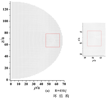
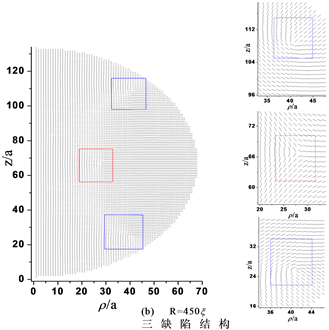
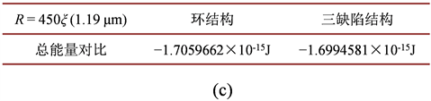
Figure 2. Director profiles about the ring structure and the structure of three defects. (a) The red square is used todescribe+1/2 ring defect, while R = 450ξ, a = 450ξ/66; (b) The blue square describes +1/2 ring defects and the red square −1/2 ring defect, while R = 450ξ, a = 450ξ/66; (c) The compared energy profile about two structures
图2. 环结构与三缺陷结构指向矢图。(a) 红色方框表示+1/2环缺陷,其中R = 450ξ, a = 450ξ/66;(b) 蓝色方框表示+1/2缺陷环,红色方框表示−1/2缺陷环,其中R = 450ξ, a = 450ξ/66;(c) 两种结构的能量对比图
图2(a)为半径1.2 μm的环结构指向矢图,以纵轴的第67格点为中心将球分割为上下两部分,会发现在离球中心大约56a附近处存在一个+1/2缺陷环(蓝色方框描述),此结构与S. Mkaddem等人提出的在较大半径下环结构为稳定态结构相符。图2(b)为发现的新结构称之为三缺陷结构,会发现缺陷的分布具有很好的对称性,即上下两个对称缺陷为+1/2环缺陷,距离球中心轴(Z轴)约40a,而中心赤道面上(分割球上下两部分)存在一个−1/2环缺陷,距离球中心约26a,此结构也满足了O. D. Lavrentovich等人提出的拓扑电荷守恒定律。通过图2(c)的能量对比说明在R = 1.19 μm半径下三缺陷结构是亚稳态,而环结构为稳态。
4.2. 三缺陷结构存在的尺寸范围
如图2所示,第一部分得到了半径为450ξ的三缺陷平衡态,我们将此半径下得到的三缺陷态作为初始态,在弹性常数 和边界条件(垂面锚定且锚定强度系数w = 10−3 J/m2)不变的情况下,选取半径为200ξ (约528 nm)、445ξ (约1.17 μm)、450ξ (约1.19 μm)、500ξ (约1.32 μm)、1000ξ (约2.64 μm)、10,000ξ (约26.4 μm),利用松弛迭代方法进行模拟计算,观察半径诱导的三缺陷态的结构变化。
如图3所示,将半径为450ξ的三缺陷态作为初始态减小半径,图3(b)当R = 445ξ时,中心赤道截面上的−1/2缺陷环向球心移动(处于球心附近处),而上下两个+1/2缺陷环向赤道面靠拢,如果继续减小半径,会发现三缺陷结构不再稳定,我们以半径为200ξ为例,下文详细描述三缺陷结构演化为+1/2缺陷环结构的动力学过程。所以给出三缺陷结构存在的最小半径为445ξ;增大半径,图3(d)当R = 500ξ时,中间部分的−1/2缺陷环向边界移动,而上下两个+1/2缺陷环也向边界靠拢;继续增大半径,图3(e)当R = 1000ξ时,三个缺陷的位置基本不在移动,继续增大半径图3(f),R = 10000ξ发现三缺陷态稳定存在且不会消失,即在较大半径的球中亚稳态三缺陷结构是稳定存在的,存在范围为R ≥ 1.17μm。
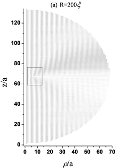


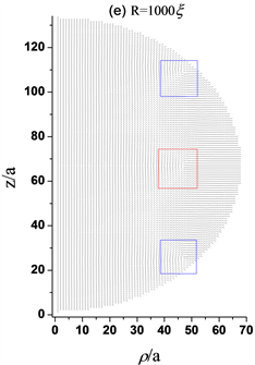
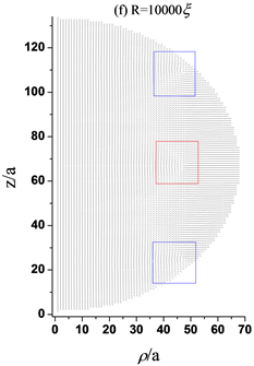
Figure 3. Director profiles about the structure of three defects with different radius. (a) The black square describes +1/2 ring defect, which is about 4a from the central axis, while R = 200ξ, a = 200ξ/66; (b) The blue squares describe +1/2 ring defects that are about 34a far from the central axis and the red square describes −1/2 ring defect that is 6a from the central axis, while R = 445ξ, a = 445ξ/66; (c) The blue squares describe +1/2 ring defects that are about 40a far from the central axis and the red square describes −1/2 ring defect that is 26a from the central axis, while R = 450ξ, a = 450ξ/66; (d) The blue squares describe +1/2 ring defects that are about 44a far from the central axis and the red square describes −1/2 ring defect that is about 42a from the central axis, while R = 500ξ, a = 500ξ/66; (e) The blue squares describe +1/2 ring defects that are about 46a far from the central axis and the red square describes −1/2 ring defect that is 45a from the central axis, while R = 1000ξ, a = 1000ξ/66; (f) The blue squares describe +1/2 ring defects that are about 46afar from the central axis and the red square describes −1/2 ring defect that is 46a from the central axis, while R = 10,000ξ, a = 10,000ξ/66
图3. 不同半径的三缺陷结构指向矢图。(a) 黑色方框描述+1/2环缺陷,距中心轴约4a,其中R = 200ξ,a= 200ξ/66;(b) 蓝色方框描述+1/2环缺陷,距中心轴约34a,红色方框描述−1/2环缺陷,距中心轴约6a,其中R = 445ξ,a = 445ξ/66;(c) 蓝色方框描述+1/2环缺陷距中心轴约40a,红色方框描述−1/2环缺陷,距中心轴约26a,其中R = 450ξ,a = 450ξ/66;(d) 蓝色方框描述+1/2环缺陷距中心轴约44a,红色方框描述−1/2环缺陷,距中心轴约42a,其中R = 500ξ,a = 500ξ/66;(e) 蓝色方框描述+1/2环缺陷距中心轴约46a,红色方框描述−1/2环缺陷,距中心轴约45a,其中R = 1000ξ,a = 1000ξ/66;(f) 蓝色方框描述+1/2环缺陷距中心轴约46a,红色方框描述−1/2环缺陷,距中心轴约46a,其中R = 10,000ξ,a = 10,000ξ/66
4.3. 边界条件对三缺陷结构的影响
上一部分已经给出了在均匀垂面锚定且锚定强度系数为w = 10−3 J/m2下三缺陷结构稳定存在的半径范围,同时我们也模拟计算了锚定强度系数为w = 10−4 J/m2、w = 10−5 /m2下三缺陷结构能稳定存在的半径范围,由于篇幅限制,只给出相应的数据结果,见表1。
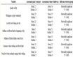
Table 1. The results of data about the stable existing structure of three defects
表1. 三缺陷结构稳定存在的数据结果
基于I-Hsin Lin [24] 等人实验研究,内毒素使得向列相球形液滴从双极结构(bipolar)转变为径向结构(radial)并不是像以往SDS等表面活性剂一样,通过均匀改变表面能W(即表面活性剂导致边界沿面锚定条件均匀转变为垂面锚定条件)从而发生转变,而是与双极结构的上下两个缺陷点相互作用,从而导致结构发生转变,基于此实验的启发,对边界锚定条件进行了适当的处理改变,应用于本文几何模型,将表面上下两个极点的锚定强度系数wmax设为最大值,并且都线性减小到中心表面处,中心表面处的锚定强度系数设为0 J/m2。
基于上述的边界条件的适当改变,选取半径为R = 1000ξ (2.64 μm),上下极点处锚定强度系数最大值分别为wmax = 10−3 J/m2、wmax = 10−4 J/m2、wmax = 10−5 J/m2对三缺陷结构进行研究,通过对比在均匀的垂面锚定边界条件下的结果,发现了一些有趣的现象。
如图4所示,对比图4(a)与图4(b)发现,图4(b)中上下两个+1/2缺陷向中心缺陷处收缩(远离边界),而中心的−1/2缺陷向球心处移动。而图4(c)与图4(d)对比,此时边界条件的变化对缺陷存在的位置无显著影响,且与图4(a)缺陷存在的位置大致相同。值得注意的是,图4(d)为上下两极点处锚定强度系数最大值,此时wmax = 10−4 J/m2,而图4(b)最大值是wmax = 10−3 J/m2,在较强的锚定作用下三个缺陷都向中心轴处收缩,说明锚定强度系数线性变化导致了这一反常现象的出现。此外,w = 10−5 J/m2与wmax = 10−5 J/m2条件下的结果均与w = 10−4 J/m2、wmax = 10−4 J/m2的结果相同,所以不再给出相应的图说明。


Figure 4. Director profiles about the three-defect structures with homeotropic anchoring on the homogenous interface and the structures with anchoring of linear variation. (a) The three-defect structures with homeotropic anchoring on the homogenous interface, w = 10−3 J/m2, R = 1000ξ, a = 1000ξ/66; (b) The three-defect structures with anchoring of linear variation, wmax = 10−3 J/m2, R = 1000ξ, a = 1000ξ/66; (c) The three-defect structures with homeotropic anchoring on the homogenous interface, w = 10−4 J/m2, R = 1000ξ, a = 1000ξ/66; (d) The three-defect structures with anchoring of linear variation, wmax = 10−4 J/m2, R = 1000ξ, a = 1000ξ/66
图4. 表面均匀垂面锚定和线性变化锚定下三缺陷结构指向矢图。(a) 均匀垂面锚定下三缺陷结构,w = 10−3 J/m2,R = 1000ξ,a = 1000ξ/66;(b) 线性变化锚定下三缺陷结构,wmax = 10−3 J/m2,R = 1000ξ,a = 1000ξ/66;(c) 均匀垂面锚定下三缺陷结构,w = 10−4 J/m2,R = 1000ξ,a = 1000ξ/66;(d) 线性变化锚定下三缺陷结构,wmax = 10−4 J/m2,R = 1000ξ,a = 1000ξ/66
4.4.结构转变的动力学过程
以R = 200ξ为例,探究随着时间的增加,三缺陷结构不再稳定,如何转变为环结构的动力学过程。
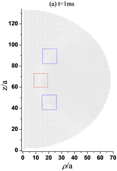

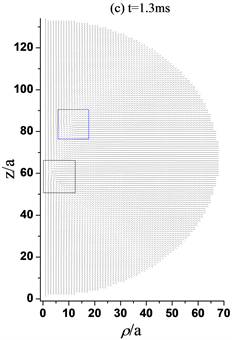


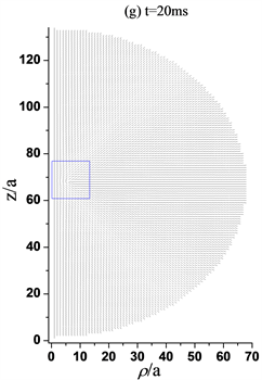
Figure 5. Director profiles about the three-defect structures transformed into the ring structure with response time increasing, while R = 200ξ, a = 200ξ/66. (a) When t = 1 ms, the three defects exist; (b) When t = 1.2 ms, the −1/2 ring defect in the lower half part begins to move rapidly towards the +1/2 ring defect; (c) When t = 1.3 ms, The −1/2 ring defect is closed to the +1/2 ring defects; (d) When t = 1.4 ms, only the +1/2 ring defect exists in the upper half part; (e) When t = 1.5 ms, +1/2 defect closes to the central axis; (f) When t = 2 ms, the +1/2 defect moves toward the core of the sphere; (g) When t = 20 ms, the +1/2 defect is stabilized at about 4a from the spherical core, forming a +1/2 ring structure
图5. 三缺陷结构随时间响应转变为环结构的指向矢图,其中R = 200ξ, a = 200ξ/66。(a) t =1 ms,三个缺陷仍存在;(b) t = 1.2 ms,下半部分−1/2环缺陷开始向+1/2环缺陷快速移动;(c) t = 1.3 ms,−1/2环缺陷与+1/2环缺陷彼此接近;(d) t = 1.4 ms,只有上半部分+1/2环缺陷存在;(e) t = 1.5 ms,+1/2缺陷向中心轴靠近;(f) t = 2 ms,+1/2缺陷向球核处移动;(g) t = 20 ms,+1/2缺陷稳定在距球核处约4a位置,形成+1/2环结构
如图5所示,随着时间的增加,三个缺陷同时向中心轴移动,图5(b)在1.2 ms时刻时,下半球的+1/2缺陷环较上半球的+1/2缺陷环开始快速向中心的−1/2缺陷环移动。图5(c)在1.3 ms时刻时,发现下半球的缺陷环与中心的缺陷环几乎融合,根据先前对于缺陷拓扑电荷的深入研究 [14] 已经得出结论,+1/2缺陷与−1/2缺陷彼此靠近会发生湮灭现象,所以图5(d)在1.4 ms时刻时,只存在上半球的一个+1/2缺陷环。与此同时,缺陷环向中心轴移动。值得注意的是,缺陷向球赤道面移动且移动缓慢,响应时间增加,图5(g)处于20 ms时刻时,+1/2缺陷环不在移动,一个处于球中心核附近的+1/2环结构稳定存在。
5. 结论
本文基于Landau-de Gennes理论,利用松弛迭代方法,研究了液晶微滴新型亚稳态三缺陷结构。该结构上下部分距离边界较近位置具有两个对称的+1/2缺陷环,中心赤道面上分布一个−1/2缺陷环,简称为液晶微滴三缺陷结构。由于模拟是在是在弹性各向同性中进行,所以指向矢结构不依赖于 角。首先探究了环结构与三缺陷结构在相同条件下同时存在的能量对比,得出环结构能量低为稳态,而三缺陷能量高为亚稳态。探究了尺寸效应对于三缺陷结构稳定存在的影响;当边界为均匀的垂面锚定,且锚定系数为定值w = 10−3 J/m2时,三缺陷结构可以稳定存在的尺寸范围是R ≥ 1.17 μm。
重点探究了改变边界条件,三缺陷结构相应的变化;首先边界仍为均匀的垂面锚定,只改变锚定强度系数w,令其为w = 10−4 J/m2,此时三缺陷结构稳定存在的尺寸范围是R ≥ 1.16 μm;当w = 10−5 J/m2时,存在的尺寸范围为R ≥ 0.95 μm;其次改变了边界锚定强度系数,使其在边界不在是定值,而是线性变化的。在球的两极点处wmax取最大值,取半径为1000ξ进行研究,其他条件相同只改变wmax的值发现,在wmax取10−3 J/m2与取10−4 J/m2、10−5 J/m2相比,反而缺陷向中心轴收缩,出现反常现象。同时发现在上述描述的范围之外三缺陷不再稳定,以R = 200ξ为例,研究了随着时间相应的增加,下半部分缺陷环向中心赤道面的−1/2缺陷环迅速移动,最终湮灭,上半部分的+1/2缺陷环则向中心轴和赤道面移动,并最终稳定在离球心核较近的位置处,形成稳定的+1/2环结构。
致谢
本课题由国家自然科学基金(11374087, 11447179)支持。作者感谢河北工业大学理学院、电子信息工程学院以及天津市材料器件重点实验室。
基金项目
国家自然科学基金(No. 11374087, No. 11447179)。
文章引用
刘宏恩,陈思博,马 鹤,周 旋,张志东. 球形向列相液滴新缺陷态的研究
Study on New Defect States of Spherical Nematic Droplet[J]. 材料科学, 2020, 10(06): 441-453. https://doi.org/10.12677/MS.2020.106054
参考文献
- 1. Jiang, J., Mcgraw, G., Ma, R., Brown, J.J. and Yang, D. (2017) Selective Scattering Polymer Dispersed Liquid Crystal Film for Light Enhancement of Organic Light Emitting Diode. Optics Express, 25, 3327-3335. https://doi.org/10.1364/OE.25.003327
- 2. Almeida, A.P., Canejo, J.P., Mur, U., Copar, S., Almeida, P., Žumer, S. and Godinho, M.H. (2019) Spotting Plants’ Microfilament Morphologies and Nanostructures. Proceedings of the National Academy of Sciences of the United States of America, 116, 13188-13193. https://doi.org/10.1073/pnas.1901118116
- 3. Aguirre, L. E., De Oliveira, A., Sec, D., Copar, S., Almeida, P., Ravnik, M., et al. (2016) Sensing Surface Morphology of Biofibers by Decorating Spider Silk and Cellulosic Filaments with Nematic Microdroplets. Proceedings of the National Academy of Sciences of the United States of America, 113, 1174-1179. https://doi.org/10.1073/pnas.1518739113
- 4. Senyuk, B., Liu, Q., He, S., Kamien, R.D., Kusner, R.B., Lubensky, T.C. and Smalyukh, I.I. (2013) Topological Colloids. Nature, 493, 200-205. https://doi.org/10.1038/nature11710
- 5. Gupta, J.K., Sivakumar, S., Caruso, F. and Abbott, N.L. (2009) Size-Dependent Ordering of Liquid Crystals Observed in Polymeric Capsules with Micrometer and Smaller Diameters. Angewandte Chemie, 48, 1652-1655. https://doi.org/10.1002/anie.200804500
- 6. Yoshioka, J., Ito, F. and Tabe, Y. (2016) Stability of a Double Twisted Structure in Spherical Cholesteric Droplets. Soft Matter, 12, 2400-2407. https://doi.org/10.1039/C5SM02838H
- 7. Peng, C. and Lavrentovich, O.D. (2015) Chirality Amplification and Detection by Tactoids of Lyotropic Chromonic Liquid Crystals. Soft Matter, 11, 7257-7263. https://doi.org/10.1039/C5SM01632K
- 8. Jeong, J., Davidson, Z.S., Collings, P.J., Lubensky, T.C. and Yodh, A.G. (2014) Chiral Symmetry Breaking and Surface Faceting in Chromonic Liquid Crystal Droplets with Giant Elastic Anisotropy. Proceedings of the National Academy of Sciences of the United States of America, 111, 1742-1747. https://doi.org/10.1073/pnas.1315121111
- 9. Wu, S.T. (2006) Fundamentals of Liquid Crystal Devices.
- 10. Mkaddem, S. and Gartland, E.C. (2000) Fine Structure of Defects in Radial Nematic Droplets. Physical Review E, 62, 6694-6705. https://doi.org/10.1103/PhysRevE.62.6694
- 11. Kim, J. and Lee, J.-H. (2018) Enhance-ment of Flexoelectric Ratio of Nematic Liquid Crystal by Doping Calamitic Ferroelectric Liquid Crystal. Liquid Crystals, 45, 1682-1689. https://doi.org/10.1080/02678292.2018.1469795
- 12. Bajc, J., Peroli, G.G., Virga, E.G. and Žumer, S. (2002) Dynamics of Nematic Point Defects in a Capillary with Tilted Boundary Conditions. Liquid Crystals, 29, 213-219. https://doi.org/10.1080/02678290110093787
- 13. Zhou, X. and Zhang, Z.D. (2014) Dynamics of Order Reconstruction in Nanoconfined Twisted Nematic Cells with aTopological Defect. Liquid Crystals, 41, 1219-1228. https://doi.org/10.1080/02678292.2014.912689
- 14. Lavrentovich, O.D. (1998) Topological Defects in Dispersed Words and Worlds around Liquid Crystals, or Liquid Crystal Drops. Liquid Crystals, 24, 117-126. https://doi.org/10.1080/026782998207640
- 15. Virga, E.G. (1994) Variational Theories for Liquid Crystals. Chapman & Hall, London. https://doi.org/10.1007/978-1-4899-2867-2
- 16. Kaiser, P., Wiese, W. and Hess, S. (1992) Stability and Instability of a Uniaxial Alignment against Biaxial Distortionsin the Isotropic and Nematic Phases of Liquid Crystals. Journal of Non-Equilibrium Thermodynamics, 17, 153-169. https://doi.org/10.1515/jnet.1992.17.2.153
- 17. Kleman, M. and Lavrentovich, O.D. (2002) Soft Matter Physics. Springer, Berlin.
- 18. Amoddeo, A., Barberi, R. and Lombardo, G. (2011) Electric Field-Induced Fast Nematic Order Dynamics. LiquidCrystals, 38, 93-103. https://doi.org/10.1080/02678292.2010.530298
- 19. Kralj, S., Rosso, R. and Virga, E.G. (2010) Finite-Size Effects on Order Reconstruction around Nematic Defects. Physical Review E, 81, 1-15. https://doi.org/10.1103/PhysRevE.81.021702
- 20. Guzmán, O., Abbott, N.L. and De Pablo, J.J. (2005) Quenched Disorder in a Liquid-Crystal Biosensor: Adsorbed Nanoparticlesat Confining Walls. The Journal of Chemical Physics, 122, 184711. https://doi.org/10.1063/1.1896354
- 21. Nolibi, M. and Durand, G. (1992) Disorientation Induced Disordering at a Nematic Liquid Crystal Solid Interface.Physical Review A, 46, 174-177. https://doi.org/10.1103/PhysRevA.46.R6174
- 22. Qian, T.-Z. and Sheng, P. (1997) Orientational States and Phase Transitions Induced by Microtextured Substrates. Physical Review E, 55, 7111-7120. https://doi.org/10.1103/PhysRevE.55.7111
- 23. Tian, Y. and Zhang, Z.D. (2015) Interaction between a + 1 Defect in a Nematic Thin Film and the Surface Wall and Flxoelectric Response at the Defect Site. Liquid Crystals, 42, 288-297. https://doi.org/10.1080/02678292.2014.984647
- 24. Lin, I., Miller, D.S., Bertics, P.J., Murphy, C.J., De Pablo, J.J. and Abbott, N.L. (2011) Endotoxin-Induced Structural Transformations in Liquid Crystalline Droplets. Science, 332, 1297-1300. https://doi.org/10.1126/science.1195639
NOTES
*通讯作者。