Modeling and Simulation
Vol.
12
No.
03
(
2023
), Article ID:
65325
,
11
pages
10.12677/MOS.2023.123198
可膨胀融合器联合后路内固定治疗颅底凹陷寰枢椎脱位的生物力学研究
蒋哲华1,王梓琦1,薛雅茹1,李富超1,陈娅羽1,刘雯1,谌诺1,袁一凡1,秦苏楠1, 马童2,赵改平1*
1上海理工大学健康科学与工程学院,上海
2同济大学附属杨浦医院骨科,上海
收稿日期:2023年3月8日;录用日期:2023年5月9日;发布日期:2023年5月16日

摘要
目的:研究颅底凹陷寰枢椎脱位(Basilar invagination with atlantoaxial dislocation, BI-AAD)采用寰枢椎可膨胀融合器和静态融合器各自联合后路内固定系统治疗的生物力学特性,为寰枢椎可膨胀融合器的设计研发提供理论依据。方法:基于BI-AAD患者术后枕颈CT图像数据结合临床手术方案,建立寰枢椎关节间可膨胀融合器(高度7~10 mm,角度5˚~8˚)联合枕骨板和C2椎弓根螺钉后路内固定(ECage + C2PS + OP)和静态融合器联合后路内固定系统(Cage + C2PS + OP)的上颈椎三维有限元模型,分析寰枢椎关节活动度、植入融合器、椎弓根螺钉系统和上下终板的应力分布等情况。结果:ECage + C2PS + OP与Cage + C2PS + OP相比在屈伸、侧弯和旋转工况下寰枢关节活动度降低了11%、33.33%、0.04%;C2终板应力峰值在四种工况下分别降低−0.01%、58.16%、47.53%、67.39%。可膨胀融合器的应力分布于壳体中间“H”部位,在不同工况下可膨胀融合器最大应力值均有所下降,最大值为后伸工况的21.38 MPa,比静态融合器降低了48.6%。而枕骨板和C2椎弓根螺钉应力整体趋势大于静态融合器组。结论:可膨胀融合器能够适用于寰枢椎特定的高度和角度的撑开调整,从而实现对颈椎生理曲度的调节。设计的可膨胀寰枢关节间融合器较静态融合器沉降率风险更低,但是撑开装置具有断裂风险需要进一步优化设计。
关键词
颅底凹陷寰枢椎脱位,可膨胀融合器,后路融合术,颈椎生物力学,有限元分析

Biomechanical Study for Treating Basilar Invagination with Atlantoaxial Dislocation by Expandable Cage Combined with Posterior Internal Fixation
Zhehua Jiang1, Ziqi Wang1, Yaru Xue1, Fuchao Li1, Yayu Chen1, Wen Liu1, Nuo Chen1, Yifan Yuan1, Sunan Qin1, Tong Ma2, Gaiping Zhao1*
1School of Health Sciences and Engineering, University of Shanghai for Science and Technology, Shanghai
2Department of Orthopedics, Yangpu Hospital Affiliated to Tongji University, Shanghai
Received: Mar. 8th, 2023; accepted: May 9th, 2023; published: May 16th, 2023

ABSTRACT
Objective: To explore the biomechanical characteristics of atlantoaxial dislocation (BI-AAD) after treatment with atlantoaxial expandable cageand static cage, respectively, in combination with posterior internal fixation systems, to provide a theoretical basis for the design and development of expandable cage of the atlantoaxial spine. Methods: Based on the postoperative occipital and cervical CT images of BI-AAD patients combined with the clinical surgical protocol, a posterior atlantoaxial expandable fusion (7~10 mm height, 5˚~8˚ angle) combined with occipital plate and C2 pedicle screw (ECage + C2PS + OP) and a static fusion combined with a posterior internal fixation system (Cage + C2PS + OP) were developed. The three-dimensional finite element models of the upper cervical spine were used to analyze the mobility of the atlantoaxial joint, the stress distribution of the implanted fusion, the pedicle screw system and the upper and lower endplates. Results: The atlantoaxial joint range of motion (ROM) was reduced by 11%, 33.33% and 0.04% in flexion-extension, lateral bending and rotation for ECage + C2PS + OP compared to Cage + C2PS + OP; the peak stresses in the C2 endplate were reduced by −0.01%, 58.16%, 47.53% and 67.39% in the four conditions, respectively. The stresses of the expandable cage were distributed in the middle “H” part of the shell, and the maximum stress value of the expandable cage decreased under different conditions, with the maximum value of 21.38 MPa in the posterior extension condition, which was 48.6% lower than that of the static cage. The overall trend of occipital plate and C2 pedicle screw stresses was greater than that of the static cage group. Conclusion: The expandable cage can be used to adjust the atlantoaxial spine at specific heights and angles, thus allowing adjustment of the cervical physiological curvature. The designed expandable inter-articular cage has a lower risk of settling rate than the static fusion, but the fracture risk of the spacer device requires further design optimization.
Keywords:BI-AAD, Expandable Cage, Posterior Fusion, Cervical Spine Biomechanics, Finite Element Analysis

Copyright © 2023 by author(s) and Hans Publishers Inc.
This work is licensed under the Creative Commons Attribution International License (CC BY 4.0).
http://creativecommons.org/licenses/by/4.0/


1. 引言
颅底凹陷寰枢椎脱位(Basilar invagination and atlantoaxial dislocation, BI-AAD)是一种复杂的颅颈交界区畸形,患者主要表现为寰椎枕骨化、寰枢椎外侧关节高度下降、寰枢椎不稳等特征。寰枢椎关节间融合器可以有效对脱位的寰枢椎进行固定融合,提高患者寰枢关节的稳定性和融合率。Goel [1] 2004年首次提出在BI-AAD患者的寰枢侧方关节间植入关节间间隔物,取得一定疗效,并在2007年对寰枢关节间隔物进一步改进,设计了特殊的锥形融合器,使其更容易插入到关节间隙 [2] 。Yin等 [3] 分析认为对于患有寰枕融合的BI-AAD患者,放入寰枢关节间植入物是必要且有效的。2016年,陈赞等 [4] [5] 提出了后路侧块关节撑开结合后路枕骨板(Occipital Plate, OP)和C2椎弓根螺钉(C2 Pedicle Screw, C2PS)进行后路固定技术,关节间融合器的支撑可有效增加寰枢椎侧方关节间隙的高度复位BI,后路固定技术可以实现后方加压复位AAD。颅底凹陷患者寰枢椎侧方关节的长度、宽度均明显小于正常人群,矢状面倾角和冠状面倾角均明显大于正常人群 [6] ,而融合器的角度和高度与终板的不匹配会增加融合器下沉和融合失败的风险 [7] [8] ,因此需要探究更适用于BI-AAD患者的可调节高度和角度的融合器。
可膨胀融合器(Expandable Cage, Ecage)在高度和角度上可以根据个体化椎体病变特征来进行调节,相比传统静态融合器更加能有效支撑和增加寰枢椎侧方关节适合的间隙和高度,体积小巧便于植入,而且能够根据病人的解剖学特点为椎体生理曲度的支撑和力学性能提供稳定性。Josha等 [9] 通过影像学和临床发现在腰椎后路椎间融合术中,可膨胀融合器相比静态融合器更有利于恢复前后椎间盘高度、椎间孔高度。Frisch等 [10] 对65名经外侧腰椎椎间融合术腰椎退行性患者进行影像学观察,可膨胀融合器组的下沉率为0%,而静态融合器组的下沉率为16%。此外,Murat等 [11] 通过体外标本生物力学研究表明,可膨胀融合器所受的终板应力与静态融合器相似,但在患者腰椎过度前凸的情况下会产生更大的终板应力。目前对于可膨胀寰枢椎关节间融合器的研究相对甚少,主要原因是颈椎寰枢关节结构的特殊性等所致。
本文基于BI-AAD患者寰枢椎侧方关节解剖学和形态学研究结果,设计一款适用于BI-AAD患者寰枢关节不同畸形病变的可调节高度和角度的融合器。结合BI-AAD患者术后枕颈CT图像数据和临床手术方案,建立寰枢椎关节间可膨胀融合器联合枕骨板和C2椎弓根螺钉后路内固定(ECage + C2PS + OP)和静态融合器联合后路内固定系统(Cage + C2PS + OP)的上颈椎三维有限元模型,分析可膨胀融合器植入寰枢关节后寰枢椎关节活动度、植入融合器、椎弓根螺钉系统和C2终板的最大von Mises应力(maximum von Mises stresses, MVMS)应力分布情况,探究寰枢椎可膨胀融合器和静态融合器各自联合后路内固定系统治疗的生物力学性能影响,评估寰枢椎可膨胀融合器结构设计和材料选择等方面存在的不足。
2. 材料与方法
2.1. 可膨胀融合器
设计的动态可膨胀寰枢关节间融合器由上下撑开壳体,基体支撑环,前后锥形螺栓及中间连接件组成。上下撑开壳体形似流线型,边角圆顿,有利于融合器的植入,上下表面设有锯齿状凸起以增加寰枢关节间的摩擦力,防止融合器在寰枢关节间发生滑脱。基体支撑环内部有两段不同长度的螺纹线,通过不同旋向和螺距的螺纹连接,以实现可膨胀融合器的高度和角度调节,同时基体支撑环内部的螺纹设计,具有一定的自锁效果,可以保证融合器在达到所需高度时保持稳定状态。此融合器前凸角度最大可调节至8˚,高度可调节范围为7~10 mm。运用三维制图软件Solidworks来实现结构的设计。融合器壳体选用和皮质骨弹性模量相似的聚醚醚酮(PEEK)材料,促进骨的植入和生长,加强骨–植入物的融合,利于骨整合和骨粘连;中间H型撑开装置选择钛合金(TI)材料进行模拟,其相比PEEK具有更强的骨传导性、在受到载荷下具有更高的抗压剪切强度 [12] 。
2.2. 建立BI-AAD患者静态和可膨胀融合器联合后路钉棒系统手术模型
选取1例合并寰枕融合畸形的难复性寰枢椎脱位的颅底凹陷病例,根据患者术后CT影像及临床手术方案,建立可膨胀融合器和静态融合器各自联合后路内固定系统手术的枕颈有限元模型。CT图像以DICOM格式导入医学处理软件Mimics,进行阈值设定、擦拭和修补等工作,并以stl格式导入到Geomagic12.0进行补洞、光洁修复等处理,运用Solidworks软件中的偏移曲面、曲线绘制、分割等功能建立椎间盘的纤维环、髓核和上下终板,其中髓核约占整个椎间盘体积的40% [13] ,厚度为0.5 mm的软骨终板构成了椎间盘的上下边界。最后将输出的igs文件导入Hypermesh 13.0进行2D、3D网格划分,将椎体分为松质骨、皮质骨、后骨三个部分,韧带以杆单元进行模拟,建立前纵韧带、后纵韧带、黄韧带、棘间韧带、棘上韧带、齿突尖韧带、翼状韧带、关节囊韧带共8种韧带。具体材料属性如表1所示 [14] [15] [16] [17] [18] 。为减少关节间相对滑动,C2~3小关节之间的接触设置为绑定,寰枢关节和寰椎前弓与齿状突关节间设置为滑动接触关系,摩擦因数为0.1 [19] 。
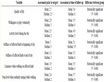
Table 1. Material properties used in the FE model of the occipitocervical spine
表1. 枕颈有限元模型各部分材料属性
建立BI-AAD患者可膨胀融合器和静态融合器分别联合C2PS + OP的枕颈三维有限元模型如图1所示,根据患者寰枢关节病变程度和寰枢关节的间隙,将融合器角度调整至4˚,高度调整至8 mm,撑开后可膨胀融合器的参数为:长18 mm、宽9 mm和高8 mm,静态融合器参数为:长18 mm,宽9 mm,高7 mm;内固定系统的几何模型为医院提供的器械参数:1) 枕骨板:长44.99 mm,高27.54 mm,厚2 mm;2) C2椎弓根螺钉:直径3.5 mm,长24 mm;3) 枕骨螺钉:直径4 mm,长8 mm,材料性质如表2所示。为提高计算的收敛性,模型建立时静态融合器和可膨胀融合器的上下撑开壳体上的锯齿结构被简化。融合器与骨质表面凹凸不平的间隙使用布尔运算,并采用共节点来模拟融合器与寰枢关节间的无微动作用,前后锥形螺栓与连接杆之间、支撑环与前后锥形螺栓之间采用共节点连接,支撑环与上下撑开壳体之间、前后锥形螺栓与上下撑开壳体之间模拟为面–面接触的绑定约束关系。


Figure 1. (a) 3D finite element models of Cage + C2PS + OP and ECage + C2PS + OP; (b) The detail of C2 cervical vertebra and cage
图1. (a) Cage + C2PS + OP和ECage + C2PS + OP三维有限元模型;(b) C2椎体融合器细节图
Table 2. Different material properties of expandable cage and implant components
表2. 可膨胀融合器和植入器械的不同材料特性
3. 结果分析
3.1. 寰枢椎关节活动度
脊柱节段ROM的表现通常被认为是决定稳定性的一个参考因素 [20] 。C2PS + OP寰枢关节间ROM在50 N集中力和1.5 N·m力矩作用下如图2(a)所示,在相同的边界和载荷条件下,与Liu [14] 等和Zhao等 [16] 有限元模型结果基本相一致,建立的术后寰枢椎脱位模型的可靠性和有效性得到验证。对比C2PS + OP的内固定模型,植入两种融合器后寰枢关节的ROM均显著降低。ECage + C2PS + OP模型在屈伸、侧弯和旋转工况下寰枢关节的活动度分别为0.28˚、0.08˚和0.21˚,相比C2PS + OP分别减小了60%、88%、78%;而Cage + C2PS + OP模型寰枢关节的ROM分别为0.25˚、0.12˚和0.20˚,分别减小64%、82%、79%。结果表明静态融合器和可膨胀融合器均使寰枢节段的稳定性得到明显提高,其中后者在侧弯工况下提供的稳定性优于前者。C2PS + OP、ECage + C2PS + OP和Cage + C2PS + OP模型中寰枢关节ROM的计算结果如图2(b)所示。
3.2. 寰枢椎可膨胀融合器和静态融合器的等效应力
BI-AAD患者实施ECage + C2PS + OP和Cage + C2PS + OP术式后在前屈、后伸、侧弯和旋转运动下可膨胀融合器和静态融合器的应力分布如图3所示。由于两种融合器的结构不同,应力分布范围有显著差异,可膨胀融合器应力主要集中在上下撑开壳体中间“H”部位,并且下撑开壳体的应力明显高于上撑开壳体,在后伸时差值最大,达到14.15 MPa;静态融合器应力则分布在融合器的四周,应力分布较广泛。观察不同工况下两种融合器的应力分布,前屈运动时所产生的应力较小,并集中在融合器中间区域,患者在做后伸、侧弯和旋转运动时,融合器所受应力偏向于运动时的受压侧,应力分布范围较广;后伸工况下,受到小关节突的抵制作用,融合器的前侧和受压侧都出现了应力集中现象,应力从中间向两端逐渐减弱。Cage + C2PS + OP 和ECage + C2PS + OP模型中融合器的最大等效应力峰值如图4所示。在前屈和旋转时两种融合器产生的最大等效应力大于后伸和侧弯。ECage + C2PS + OP的应力峰值分别为7.83 MPa、21.38 MPa、20.73 MPa、12.47 MPa,对比Cage + C2PS + OP在各种工况下都有降低,其中后伸工况最为明显达到48.6%。

Figure 2. (a) Comparison of calculation results in C2PS + OP atlantoaxial ROM; (b) Comparison of the atlantoaxial ROM in the C2PS + OP, Cage + C2PS + OP, ECage + C2PS + OP model under flexion-extension, lateral bending and axial rotation
图2. (a) C2PS + OP寰枢关节间ROM结果比较;(b) C2PS + OP、Cage + C2PS + OP和ECage + C2PS + OP和在屈伸、侧弯和旋转运动时寰枢关节的ROM比较

Figure 3. The von Mises stress contour plot of cage in ECage + C2PS + OP model and Cage + C2PS + OP model under flexion, extension, lateral bending, and axial rotation
图3. ECage + C2PS + OP 和Cage + C2PS + OP模型在前屈、后伸、侧弯和旋转下融合器应力云图

Figure 4. Comparison of the maximum von Mises stress for cage of Cage + C2PS + OP model and ECage + C2PS + OP model
图4. Cage + C2PS + OP和ECage + C2PS + OP模型融合器的最大等效应力比较
3.3. C2终板的等效应力
终板的损伤塌陷是融合器沉降的重要原因 [21] ,因此分析C2终板应力可以更好判断两种融合器塌陷的可能性。ECage + C2PS + OP和Cage + C2PS + OP模型在不同工况下C2终板应力分布如图5所示。由图可见,Cage + C2PS + OP与ECage + C2PS + OP相比,相同工况下更容易产生应力集中现象。两种模型的C2终板应力分布相似,在旋转工况下应力分布于整个C2终板,应力集中现象不明显;其他工况的应力主要位于椎体的受压侧,集中在椎体终板的前后部,符合人体生物力学特点:终板的中间部分是终板最薄弱的部分,而后外侧强度最高 [22] 。

Figure 5. The von Mises stress contour plot of C2 in Cage + C2PS + OP model and ECage + C2PS + OP model under various motions
图5. Cage + C2PS + OP和ECage + C2PS + OP模型在不同工况下中C2终板应力
观察ECage + C2PS + OP和Cage + C2PS + OP模型的应力峰值,在前屈运动下两种模型无显著性差异;其他三种工况Cage + C2PS + OP的C2终板应力峰值都比ECage + C2PS + OP较高,其中在旋转工况下的差距最为明显。C2终板MVMS在Cage + C2PS + OP和ECage + C2PS + OP相比的比率分别为:前屈:0.98:1;后伸:1.36:1;侧弯:1.91:1和旋转:3.06:1。综上所述,植入可膨胀融合器模型的C2终板应力相比植入静态融合器模型更小,可以进一步地降低融合器下沉的风险。
3.4. 钉棒系统的应力分布
临床上C2PS、OP等钉棒系统已被广泛用于治疗BI-AAD患者,而采用不同的融合器时,钉棒系统对力的传导能力会发生改变。图6为ECage + C2PS + OP和Cage + C2PS + OP模型在前屈、后伸、侧弯和旋转工况下钉棒系统的应力分布云图。两种融合器模型中钛棒和枕骨板的应力分布范围和应力变化趋势相似,钛棒下部为应力主要集中部位,屈伸和旋转运动下,枕骨板应力相对均匀地分布在枕骨螺钉周围,在侧弯时,应力向枕骨板受压侧集中,且枕骨螺钉承受应力较不明显。C2椎弓根螺钉在不同模型下应力分布有所不同,ECage + C2PS + OP模型中分散于整个椎弓根螺钉,而Cage + C2PS + OP模型中应力主要在螺钉–骨界面集中。

Figure 6. The von Mises stress contour plot of screw-rod system in the ECage + C2PS + OP model and Cage + C2PS + OP model
图6. ECage + C2PS + OP和Cage + C2PS + OP模型中钉棒系统应力云图

Figure 7. Maximum stress on C2 pedicle screw, occipital plate and titanium rod under ECage + C2PS + OP model, Cage + C2PS + OP model (A1, A2, A3: ECage + C2PS + OP, B1, B2, B3: Cage + C2PS + OP)
图7. ECage + C2PS + OP、Cage + C2PS + OP模型中C2椎弓根螺钉,枕骨板和钛棒的最大应力值(A1、A2、A3:ECage + C2PS + OP组,B1、B2、B3:Cage + C2PS + OP组)
可膨胀融合器和静态融合器中钉棒系统整体而言在前屈时MVMS较其他工况小,后伸时呈现最大趋势。观察钉棒系统各部分应力(如图7所示),钛棒和枕骨板在ECage + C2PS + OP模型中应力峰值均高于Cage + C2PS + OP模型,在前屈、后伸、侧弯和旋转工况下分别升高27.67%,45.20%,36.54%和47.05%;7.90%,39.24%,19.90%和30.21%。ECage + C2PS + OP组C2椎弓根螺钉较Cage + C2PS + OP模型,在后伸和旋转条件下应力分别升高了15.99%和22.84%,在前屈和侧弯工况下降低了16.57%和9.28%。两个模型中钛棒承受的应力均高于椎弓根螺钉和枕骨板,尤其是在旋转运动下钛棒下端所承受的最大应力为枕骨板的2倍左右为48.81 MPa。
4. 讨论
融合复位技术在临床上被广泛应用于医治BI-AAD患者并取得很好的疗效。相比单纯的后路内固定,Cage的增加可以增强插入关节空间后的旋转稳定性,保持寰枢椎间高度,并在压缩时使植骨与上下关节面紧密接触,增加融合率 [23] 。2004年Goel [1] 首次提出BI-AAD患者植入金属垫片或自体髂嵴骨并用侧块螺钉固定,多数患者实现了不同程度的复位。Chandra等 [24] 和Salunke等 [25] 使用关节打磨技术将倾斜的C1-2小关节面钻孔直到它们平行,并放入关节间融合器,可以将不可复性的AAD转化为可复性的AAD。Duan [26] 等提出通过关节撑开、融合器复位的内固定方法可以有效保护BI-AAD患者的C2关节面,并降低破坏皮质骨的风险。本课题组Zhao等 [16] 使用有限元方法,验证了Cage + C2PS + OP固定不仅可以增加寰枢关节的稳定性,而且可以减少螺钉和钢板的断裂和松动,提高后路技术的复位率。但植入的融合器高度过大,会提高融合器下沉的风险,高度偏小,则无法补充寰枢椎间原本的高度,达不到复位BI的目的 [27] 。可膨胀融合器已在腰椎手术中有不同程度的应用,与静态融合器相比,允许在折叠状态下插入和原位扩张,增加了与椎体上终板的接触面积,减少了椎弓根压缩时下终板的后移,具有最大限度恢复脊椎前凸的潜力,但是在撑开过程中会承受到更大的撑开力,存在着终板下沉的风险 [28] [29] [30] 。本研究设计了一款可膨胀寰枢椎关节间融合器,通过对高度和角度的调节使融合器更贴合BI-AAD患者的寰枢椎侧方关节,探究可膨胀和静态寰枢椎关节间融合器对于BI-AAD患者生物力学性能的影响,为可膨胀寰枢椎关节间融合器的进一步优化设计提供基础。
有限元结果显示,对BI-AAD患者分别实施Cage + C2PS + OP和ECage + C2PS + OP内固定术后,上颈椎稳定性较C2PS + OP固定下的BI-AAD显著提高。ECage + C2PS + OP固定方式在侧弯时稳定性较好,后伸时稳定性较Cage + C2PS + OP稍差,但各工况下ROM差异均小于0.1˚,对临床上的效果不会产生显著性差异。
Cage和终板在各运动状态下所受载荷越低,其发生沉降的可能性越小 [22] 。分析比较融合器和C2终板的应力结果,所设计的可膨胀寰枢椎关节间融合器所受应力均小于静态融合器,由于设计的可撑开结构角度和高度可调节使融合器增加了Cage与上下椎体表面的接触面积,在运动时可更好的将所受负荷分散于上下椎体。在各种工况下可膨胀融合器最大的承受载荷为21.38 MPa,静态融合器最大的承受载荷为40.26 MPa,最小承受载荷为13.80 MPa,两种融合器所受载荷都远低于PEEK材料的破坏载荷95.2 MPa [27] ,因此所承受的载荷对融合器本身破坏风险较小,但值得注意的是可撑开融合器应力主要集中在上下撑开壳体中间“H”部位,意味着撑开组件承受着较大的应力,有断裂和撑开失败的风险,在后续的研究中可以选用硬度更高的材料或者对结构进行优化。
C2PS + OP可以对BI-AAD患者后路进行良好的固定,并且相比传统的C1LMS + C2PS在手术中有更大的空间进行操作,更容易进行牵引、悬臂和复位 [31] 。分析比较植入两种融合器后的内固定系统,Cage + C2PS + OP的椎弓根应力主要集中在螺钉和C2椎骨,椎弓根螺钉尾侧存在明显的应力集中,这一现象与Chen等 [32] 发现头侧螺钉的轴向应力低于尾侧螺钉,螺钉–骨界面附近的应力较高,从而导致螺钉疲劳失效的骨折特征一致。ECage + C2PS + OP与其相比在后伸和旋转工况下所受的应力峰值更大,但是应力分散于整个椎弓根螺钉,断裂风险较小。ECage + C2PS + OP钛棒和枕骨板所受应力均大于Cage + C2PS + OP,但远远小于Zhao [16] 等人未放入融合器的C2PS + OP模型的有限元模拟结果,这表明两款融合器都可以分散后路内固定系统所受压力,降低器械断裂风险,但静态融合器相比所设计可膨胀寰枢椎关节间融合器对于分散器械载荷有更大的优势。
本研究的局限性如下:① 由于寰枢侧块关节较小,并且可撑开结构较为复杂,因此设计的寰枢椎侧块关节间融合器的植骨空间仅有“H”型区域外围的空间,植骨空间可能存在不足;② 研究中有限元方法分析取得的是瞬时的生物力学数据,忽略了内部撑开机构的抗疲劳特性,需要进一步完善内固定器械疲劳试验、断裂试验等;③ C0~C3的三维有限元模型与正常生物体有着一定的差距,无法模拟肌肉、软组织等结构的真实影响,需要进一步的体内和体外的实验测试的验证。
5. 结论
本研究所设计的可膨胀融合器能够适用于寰枢椎特定的高度和角度的撑开调整,从而实现对颈椎生理曲度的调节。设计的可膨胀寰枢关节间融合器较静态融合器沉降率风险更低,但是撑开装置具有断裂风险需要进一步优化设计。
基金项目
国家自然科学基金(11502146);上海市市建委科研课题201940249,北京市医院管理中心临床医学发展专项经费(XMLX202138)。
文章引用
蒋哲华,王梓琦,薛雅茹,李富超,陈娅羽,刘 雯,谌 诺,袁一凡,秦苏楠,赵改平,马 童. 可膨胀融合器联合后路内固定治疗颅底凹陷寰枢椎脱位的生物力学研究
Biomechanical Study for Treating Basilar Invagination with Atlantoaxial Dislocation by Expandable Cage Combined with Posterior Internal Fixation[J]. 建模与仿真, 2023, 12(03): 2162-2172. https://doi.org/10.12677/MOS.2023.123198
参考文献
- 1. Goel, A. (2004) Treatment of Basilar Invagination by Atlantoaxial Joint Distraction and Direct Lateral Mass Fixation. Journal of Neurosurgery: Spine, 1, 281-286. https://doi.org/10.3171/spi.2004.1.3.0281
- 2. Atul Goel, M.C.H. (2007) Atlantoaxial Joint Jamming as a Treatment for Atlantoaxial Dislocation: A Preliminary Report. Technical Note. Journal of Neurosurgery: Spine, 7, 90-94. https://doi.org/10.3171/SPI-07/07/090
- 3. Yin, Y.-H., Yu, X.-G., Qiao, G.-Y., et al. (2014) C1 Lateral Mass Screw Placement in Occipitalization with Atlantoaxial Dislocation and Basilar Invagination: A Report of 146 Cases. Spine, 39, 2013-2018. https://doi.org/10.1097/BRS.0000000000000611
- 4. Chen, Z., Duan, W., Chou, D., et al. (2020) A Safe and Effective Posterior Intra-Articular Distraction Technique to Treat Congenital Atlantoaxial Dislocation Associated with Basilar Invagina-tion: Case Series and Technical Nuances. Operative Neurosurgery (Hagerstown), 20, 334-342. https://doi.org/10.1093/ons/opaa391
- 5. 段婉茹, 刘振磊, 关键, 等. 应用宣武枕颈复位内固定系统一期后路手术治疗颅底凹陷寰枢椎脱位临床报告[J]. 中华外科杂志, 2019, 57(10): 782-787.
- 6. 赵兴华, 夏之远, 菅凤增, 等. 适用于BI-AAD患者的寰枢椎侧块关节融合器的研究与设计[J]. 中华神经外科疾病研究杂志, 2017, 16(6): 485-489.
- 7. Mohammad-Shahi, M.H., Nikolaou, V.S., Giannitsios, D., et al. (2013) The Effect of Angular Mismatch be-tween Vertebral Endplate and Vertebral Body Replacement Endplate on Implant Subsidence. Clinical Spine Surgery, 26, 268-273. https://doi.org/10.1097/BSD.0b013e3182425eab
- 8. Tan, J.-S., Bailey, C.S., Dvorak, M.F., et al. (2005) In-terbody Device Shape and Size Are Important to Strengthen the Vertebra-Implant Interface. Spine, 30, 638-644. https://doi.org/10.1097/01.brs.0000155419.24198.35
- 9. Woodward, J., Koro, L., Richards, D., et al. (2022) Expandable versus Static Transforaminal Lumbar Interbody Fusion Cages: 1-Year Radiographic Parameters and Patient-Reported Outcomes. World Neurosurgery, 159, E1-E7. https://doi.org/10.1016/j.wneu.2021.11.056
- 10. Li, Y.M., Frisch, R.F., Huang, Z., et al. (2020) Comparative Effective-ness of Expandable versus Static Interbody Spacers via MIS LLIF: A 2-Year Radiographic and Clinical Outcomes Study. Glob-al Spine Journal, 10, 998-1005. https://doi.org/10.1177/2192568219886278
- 11. Pekmezci, M., Tang, J.A., Cheng, L., et al. (2012) Comparison of Ex-pandable and Fixed Interbody Cages in a Human Cadaver Corpectomy Model, Part I: Endplate Force Characteristics. Journal of Neurosurgery: Spine, 17, 321-326. https://doi.org/10.3171/2012.7.SPINE12171
- 12. Campbell, P.G., Cavanaugh, D.A., Nunley, P., et al. (2020) PEEK ver-sus Titanium Cages in Lateral Lumbar Interbody Fusion: A Comparative Analysis of Subsidence. Neurosurgical Focus, 49, E10. https://doi.org/10.3171/2020.6.FOCUS20367
- 13. Zhao, G., Wu, K., Liu, D., et al. (2021) A Biomechanical Study of Proximal Junctional Kyphosis after Posterior Long Segment Fusion with Vertebral Body Augmentation. Clinical Biomechanics, 87, Article ID: 105415. https://doi.org/10.1016/j.clinbiomech.2021.105415
- 14. Liu, H., Zhang, B., Lei, J., et al. (2016) Biomechanical Role of the C1 Lateral Mass Screws in Occipitoatlantoaxial Fixation: A Finite Element Analysis. Spine, 41, E1312-E1318. https://doi.org/10.1097/BRS.0000000000001637
- 15. Zhang, B.-C., Liu, H.-B., Cai, X.-H., et al. (2015) Biomechanical Comparison of a Novel Transoral Atlantoaxial Anchored Cage with Established Fixation Technique—A Finite Element Analy-sis. BMC Musculoskeletal Disorders, 16, Article No. 261. https://doi.org/10.1186/s12891-015-0662-7
- 16. Zhao, G., Song, M., Duan, W., et al. (2022) Biomechanical Investigation of Intra-Articular Cage and Cantilever Technique in the Treat-ment of Congenital Basilar Invagination Combined with Atlantoaxial Dislocation: A Finite Element Analysis. Medical & Bio-logical Engineering & Computing, 60, 2189-2199. https://doi.org/10.1007/s11517-022-02596-y
- 17. Zafarparandeh, I., Erbulut, D.U. and Ozer, A.F. (2016) Influence of Three-Dimensional Reconstruction Method for Building a Model of the Cervical Spine on Its Biomechanical Responses: A Fi-nite Element Analysis Study. Advances in Mechanical Engineering, 8, 1-6. https://doi.org/10.1177/1687814016638809
- 18. Lee, S.-H., Im, Y.-J., Kim, K.-T., et al. (2011) Comparison of Cervical Spine Biomechanics after Fixed- and Mobile-Core Artificial Disc Replacement: A Finite Element Analysis. Spine, 36, 700-708. https://doi.org/10.1097/BRS.0b013e3181f5cb87
- 19. Helgeson, M.D., Lehman Jr., R.A., Sasso, R.C., et al. (2011) Bio-mechanical Analysis of Occipitocervical Stability Afforded by Three Fixation Techniques. The Spine Journal, 11, 245-250. https://doi.org/10.1016/j.spinee.2011.01.021
- 20. Panjabi, M.M. (1992) The Stabilizing System of the Spine. Part I. Function, Dysfunction, Adaptation, and Enhancement. Journal of Spinal Disorders, 5, 383. https://doi.org/10.1097/00002517-199212000-00001
- 21. Li, H.-M., Zhang, R.-J. and Shen, C.-L. (2019) Radiographic and Clinical Outcomes of Oblique Lateral Interbody Fusion versus Minimally Invasive Transforaminal Lumbar Interbody Fu-sion for Degenerative Lumbar Disease. World Neurosurgery, 122, e627-e638. https://doi.org/10.1016/j.wneu.2018.10.115
- 22. Hou, Y. and Luo, Z. (2009) A Study on the Structural Properties of the Lumbar Endplate: Histological Structure, the Effect of Bone Density, and Spinal Level. Spine, 34, E427-E433. https://doi.org/10.1097/BRS.0b013e3181a2ea0a
- 23. Li, S., Ni, B., Xie, N., et al. (2010) Biomechanical Evaluation of an Atlantoaxial Lateral Mass Fusion Cage with C1-C2 Pedicle Fixation. Spine, 35, E624-E632. https://doi.org/10.1097/BRS.0b013e3181cf412b
- 24. Chandra, P.S., Prabhu, M., Goyal, N., et al. (2015) Distraction, Compression, Extension, and Reduction Combined with Joint Remodeling and Extra-Articular Distraction: Description of 2 New Modifications for Its Application in Basilar Invagination and Atlantoaxial Dislocation: Prospective Study in 79 Cases. Neurosurgery, 77, 67-80. https://doi.org/10.1227/NEU.0000000000000737
- 25. Salunke, P., Sahoo, S.K., Deepak, A.N., et al. (2016) Redefining Congenital Atlantoaxial Dislocation: Objective Assessment in Each Plane before and after Operation. World Neurosurgery, 95, 156-164. https://doi.org/10.1016/j.wneu.2016.07.097
- 26. Duan, W., Liu, Z., Guan, J., et al. (2019) Reduction of the Atlantoaxial Dislocation Associated with Basilar Invagination through Single-Stage Posterior Approach: Using Xuanwu Occipital-Cervical Reduction Surgical Suite. Chinese Journal of Surgery, 57, 63-68.
- 27. 张童童, 董恩纯, 郑纪豹, 等. 3D打印高度可调聚醚醚酮颈椎椎间融合器的优化设计与评价[J]. 医用生物力学, 2021, 36(2): 177-183.
- 28. Mulvaney, G., Monk, S., Clemen-te, J.D., et al. (2020) Expandable Interbody Spacers: A Two-Year Study Evaluating Radiologic and Clinical Outcomes with Pa-tient-Reported Outcomes. International Journal of Spine Surgery, 14, S31-S38. https://doi.org/10.14444/7124
- 29. Vaishnav, A.S., Saville, P., McAnany, S., et al. (2020) Retrospective Review of Im-mediate Restoration of Lordosis in Single-Level Minimally Invasive Transforaminal Lumbar Interbody Fusion: A Comparison of Static and Expandable Interbody Cages. Operative Neurosurgery, 18, 518-523. https://doi.org/10.1093/ons/opz240
- 30. Godzik, J., Lehrman, J.N., Newcomb, A.G., et al. (2019) Tailoring Selection of Transforaminal Interbody Spacers Based on Biomechanical Characteristics and Surgical Goals: Evaluation of an Expandable Spacer. Journal of Neurosurgery: Spine, 32, 383-389. https://doi.org/10.3171/2019.1.SPINE181008
- 31. Duan, W., Du, Y., Qi, T., et al. (2019) The Value and Limitation of Cervical Traction in the Evaluation of the Reducibility of Atlantoaxial Dis-location and Basilar Invagination Using the Intraoperative O-Arm. World Neurosurgery, 132, e324-e332. https://doi.org/10.1016/j.wneu.2019.08.160
- 32. Chen, C.S., Chen, W.J., Cheng, C.K., et al. (2005) Failure Analysis of Broken Pedicle Screws on Spinal Instrumentation. Medical Engineering & Physics, 27, 487-496. https://doi.org/10.1016/j.medengphy.2004.12.007
NOTES
*通讯作者。