Journal of Oil and Gas Technology
Vol.
44
No.
01
(
2022
), Article ID:
49883
,
14
pages
10.12677/JOGT.2022.441008
不同工况下井筒中油气水三相流型预测研究
池明1*,马文敏2,黄超3,郭玲1,杜军军1,关子越1
1中国石油新疆油田公司工程技术研究院,新疆 克拉玛依
2昆明理工大学化学工程学院,云南 昆明
3中国石油新疆油田公司风城油田作业区,新疆 克拉玛依
收稿日期:2022年2月8日;录用日期:2022年3月22日;发布日期:2022年3月30日

摘要
为改善井筒中三相流流型划分不精确的实际状况,本文采用室内实验与理论研究相结合的方法针对不同倾角、气液比工况下井筒中油气水三相流型开展了详细研究。通过分析研究发现,不同工况下倾斜管及垂直管中油气水三相流流型总体上呈现气泡流、段塞流、搅动流、环雾流四种流型;基于此建立了油气水三相流流型划分综合有效模型,并明确了泡状流–段塞流、段塞流–搅动流、以及搅动流–环雾流的流型转换界限模型;通过实验数据检验该模型发现研究得出的不同倾角流型划分方法与实验结果吻合良好。本研究中油气水三相流流型划分综合方法可为井筒中油气水三相流流型划分及压力预测提供依据。
关键词
井筒,油气水多相流型,流型界限

Research on Multiphase Flow Pattern Prediction of Oil-Gas-Water Phase in the Wellbore under Different Conditions
Ming Chi1*, Wenmin Ma2, Chao Huang3, Ling Guo1, Junjun Du1, Ziyue Guan1
1Engineering Technology Research Institute of PetroChina Xinjiang Oilfield Company, Karamay Xinjiang
2Department of Chemical Engineering, Kunming University of Science and Technology, Kunming Yunnan
3Fengcheng Oilfield Operation Area of PetroChina Xinjiang Oilfield Company, Karamay Xinjiang
Received: Feb. 8th, 2022; accepted: Mar. 22nd, 2022; published: Mar. 30th, 2022

ABSTRACT
In order to improve the actual situation of inaccurate division of the three-phase flow pattern in the wellbore, this paper uses a combination of laboratory experiments and theoretical research to carry out a detailed study of the oil-gas-water three-phase flow pattern in the wellbore under different inclination angles and gas-liquid ratio conditions. Through analysis and research, it is found that the three-phase flow patterns of oil, gas and water in inclined pipes and vertical pipes generally present four flow patterns of bubble flow, slug flow, agitation flow and annular mist flow under different working conditions. A comprehensive and effective model for the division of phase flow and flow pattern was established, and the flow pattern transition boundary models of bubble flow-slug flow, slug flow-stirring flow, and agitation flow-annular mist flow were clarified. The obtained flow pattern division method with different inclination angles is in good agreement with the experimental results. The comprehensive method of the three-phase flow pattern division of oil, gas and water in this study can provide a basis for the flow pattern division and pressure prediction of the three-phase flow pattern of oil, gas and water in the wellbore.
Keywords:Wellbore, Flow Pattern of Oil-Gas-Water Phase, Flow Boundary

Copyright © 2022 by author(s) and Hans Publishers Inc.
This work is licensed under the Creative Commons Attribution International License (CC BY 4.0).
http://creativecommons.org/licenses/by/4.0/


1. 引言
不同工况下井筒中油气水三相流型预测是准确开展井筒多相流压力计算的基础,按照不同的流动形态来研究气液两相流的规律,是目前常用的方法 [1]。迄今,在研究流型方面,不同的研究者用了快速摄影、探针等多种方法,但流型的划分总归还是靠人的肉眼观察判断 [2]。不同的学者对流型的观察理解不同,流型的划分也有所不同 [3] [4]。目前对于垂直上升管中的流型划分就有几十种,部分常用的流型划分方法如表1。
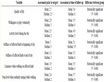
Table 1. Common flow pattern division methods for vertical wells
表1. 垂直井常用流型划分方法
井筒中油气水三相流流型划分方法众多,适应性各不相同,需要进一步展开特定研究,以期明确井筒中三相流流型状况,并建立流型划分综合有效模型及流型划分界限,为实际方案制定及决策优化提供依据 [12] [13] [14]。
本文采用室内实验与理论研究相结合的方法针对不同倾角、气液比工况下井筒中油气水三相流型开展了详细研究,在明确不同工况下倾斜管及垂直管中油气水三相流流型总体分布基础上,通过实验结果分析气液多相管流机理研究,结合现有井筒油气水三相流流型划分界限建立了流型综合划分模型,并检 验了该模型的有效性。
2. 实验方法与实验介质
2.1. 实验方法
室内实验采用中石油气举实验基地多相流实验平台,将一定比例的油、气、水三相通过泵注入实验管柱,观察流体流型,测实验管段压差、持液率、粘度、气液比等参数。实验管柱倾角、流体粘度、流体温度、含水率、气液比等按实际条件调节。
2.2. 实验装置及参数
1) 实验设备
中石油气举实验基地多相流实验平台可以开展油、气、水等多种流体,在30˚~90˚倾角、常温90℃,常压3.5 MPa、液流量0~500 m3/d,流体粘度0~1000 mPa∙s、气流量0~50000 m3/d范围内多相流动态研究。实验装置及流程示意图如图1所示。

Figure 1. Flow chart of multiphase flow experimental device
图1. 多相流实验装置流程图
2) 实验参数
为了掌握流体流型变化规律,需要挖掘大量实验基础数据。根据特定气井生产数据结合相似原理确定实验条件,在增加多种条件下的测试内容,实验参数为25℃、0.5 MPa下,含水率(%)分别为20、60、100,液量(m3/d)分别为3、5、10、15,倾角(˚)为30、60、90,气液比(m3/m3)为1000、2000。
3. 不同工况井筒油气水三相流流型研究
油气水三相在井筒流动过程中,各相的相对数量和分布状态不同会形成不同流型,而不同的流型具有不同的流动规律。研究流型明确井筒中详细的流动物理现象,构建反映物理现象本质的、更为准确的关联方程,从而提出更好的理论模型指导实际应用。
3.1. 不同工况井筒多相流流型实验流型
基于对多相管流流型的调研及前期研究,实验过程中依托观察与高速摄像机结合的方法准确判断流型,实验过程中针对不同倾角、不同气液比开展重复实验,发现倾斜管及垂直管的主要流型为:
1) 倾斜管:气泡流、段塞流、搅动流、环雾流;
2) 垂直管:气泡流、段塞流、搅动流、环雾流。
倾斜管和垂直管的流型相似,倾斜管和垂直管流型图片如图2所示。
 (a)
(a)
 (b)
(b)
 (c)
(c)
 (d)
(d)
Figure 2. Flow pattern picture of inclined pipe (vertical pipe). (a) bubbly flow; (b) slug flow; (c) churn flow; (d) circumferential fog flow
图2. 倾斜管(垂直管)流型图。(a) 气泡流;(b) 段塞流;(c) 搅动流;(d) 环雾流
3.2. 实验条件下流型划分研究
通常为了表征多相流研究中如管径、流量、气液比、压力、温度等相关参数共同对流型的影响,一般采用液体表观流速和气体表观流速来对多相流的流动规律进行研究 [15] [16]。为了得到不同倾角、气液比条件下流型变化规律,首先以液体表观流速为纵坐标,气体表观流速为横坐标,采用对数坐标,在借鉴各研究学者给出的流型划分界限基础上,给出实验条件下不同流型之间的划分界限 [17]。
不同研究学者对斜井中的气液两相流动进行了研究,并且都给出了综合机理模型。综合机理模型能够预测直井以及斜井中的流型。由于机理模型是从流动的机理出发,具有较好的适用性,因此,借鉴已有的流型划分方法来确定实验条件下的流型划分界限 [18] [19] [20]。
1) 泡状流与段塞流之间的转变
Kaya等人 [21] 通过总结和分析泡状流的流动特性,给出了泡状流向段塞流的转变界限公式:
(2-1)
式中:vsg——气体表观流速,m/s;vsl——液体表观流速,m/s; ——空隙率; ——液相密度,kg/m3; ——液相密度,kg/m3; ——倾斜角度,˚。
泰特尔等人 [9] 通过实验指出,空隙 可作为泡状流到段塞流的转变界限,因此,泡状流到段塞流的转变界限为:
(2-2)
式中:vsg——气体表观流速,m/s;vsl——液体表观流速,m/s; ——液相密度,kg/m3; ——液相密度,kg/m3; ——倾斜角度,˚; ——表面张力,mN/m。
将实验观察到的泡流和段塞流与巴尼 [10] 等人泡状流与段塞流的转变界限绘制在同一图上,30˚、60˚、90˚的流型划分界限和数据如图3、图4、图5所示。

Figure 3. The boundary division of bubble flow and slug flow at an inclination angle of 30˚
图3. 倾角30˚泡流–段塞流界限划分

Figure 4. The boundary division of bubble flow and slug flow at an inclination angle of 60˚
图4. 倾角60˚泡流–段塞流界限划分

Figure 5. Boundary division of bubble flow and slug flow at an inclination angle of 90˚
图5. 倾角90˚泡流–段塞流界限划分
从图中可以看出,给出的泡流–段塞流流型划分界限与实验得出的泡流与段塞流的转变相符得较好。
2) 段塞流与搅动流之间的转换
坦格斯达尔等 [22] 详尽地研究了扰动流,根据飘移流动方法建立了一个新的适合于铅直和倾斜管线的转变准则,段塞单元的总体空隙度为:
(2-3)
式中的泰勒气泡 [23] 上升速度 表示为:
(2-4)
式中:D为管径,m;其他同前。
坦格斯达尔等 [22] 提出,用段塞单元的总体积空隙率代替泰勒气泡区的空隙率来表征这一转变,将 代入,可得段塞流到搅动流的转变界限,即
(2-5)
(2-6)
Kaya等人 [21] 采用欧文的实验结果,即认为泰勒气泡区的空隙率约为0.78,段塞流会向搅动流转变,得出的段塞流到扰流的界限为:
(2-7)
将实验观察到的段塞流和搅动流与段塞流和搅动流的转变界限绘制在同一图上,30˚、60˚、90˚的流型划分界限和数据如图6、图7、图8所示。

Figure 6. The boundary division of slug flow and agitated flow at an inclination angle of 30˚
图6. 倾角30˚段塞流–搅动流界限划分

Figure 7. Slug flow-disturbing flow boundary division at an angle of 60˚
图7. 倾角60˚段塞流–搅动流界限划分

Figure 8. The boundary division of slug flow and agitated flow at an inclination angle of 90˚
图8. 倾角90˚段塞流–搅动流界限划分
从图中可以看出,段塞流–搅动流流型划分界限(常用的方法 [24] )与实验条件下观察到的段塞流与搅动流的转变基本相符。因此,选用段塞流–搅动流流型划分界限相关式作为本实验段塞流与搅动流流型划分界限。
3) 搅动流与环雾流之间的转换
Hasan和Kabir [11] 通过对铅直管中气液两相流动流型转变的机理分析,得出了判别扰流与环雾流的判别准则,并提出判别方法。根据液滴在拖拽力和重力之间平衡原理,结合Turner [25] 研究成果可以得出在铅直井筒中,流型转变界限如下:
(2-8)
此界限只适用于垂直管,实验中需要考虑角度,因此先根据不同角度、不同含水率条件下的流行转变的平均值,再对公式进行拟合,进而得到搅动流与环雾流的转变界限。不同倾角、不同含水率搅动流–环雾流转变气体表观速度如表2所示。
Table 2. The apparent velocity of gas at different inclination angles and different water content of agitated flow-annular flow transition
表2. 不同倾角、不同含水率搅动流–环状流转变气体表观速度
经过拟合得到搅动流与环雾流的转变界限为:
(2-9)
将实验过程中的搅动流和环雾流与拟合出的搅动流和环雾流转变界限绘制在同一图上,不同角度的流型界限如图9、图10、图11所示。

Figure 9. Delimitation of agitating flow-circular fog flow at an inclination angle of 30˚
图9. 倾角30˚搅动流–环雾流界限划分

Figure 10. Boundary division of agitating flow- circular fog flow at an inclination angle of 60˚
图10. 倾角60˚搅动流–环雾流界限划分

Figure 11. Boundary division of agitated flow at an inclination angle of 90˚-circular fog flow
图11. 倾角90˚搅动流–环雾流界限划分
4. 流型划分综合模型检验
在前人的研究成果基础上 [26],依据实验数据,得出了如下流型划分综合模型如下:
泡状流到段塞流的转变界限为:
(3-1)
段塞流到搅动流的界限为:
(3-2)
搅动流与环雾流的转变界限为:
(3-3)
将不同条件下实验观察得到的流型数据和流型划分模型绘制出来,如图12到图20所示。由图可以看出,给出的流型划分界限与实验数据吻合较好。
综合前人的研究成果和本研究所得实验数据,修正了泡状流–段塞流、段塞流–搅动流、以及搅动流–环雾流的流型转换界限模型;通过将流型转换界限模型与实验数据的对比分析,表明研究得出的不同倾角流型划分综合模型与实验结果吻合良好。

Figure 12. Dividing boundary of flow pattern with inclination angle of 30˚ and water content of 20%
图12. 倾角30˚、含水20%流型划分界限

Figure 13. Dividing boundary of flow pattern with inclination angle of 30˚ and water content of 60%
图13. 倾角30˚、含水60%流型划分界限

Figure 14. Dividing boundary of flow pattern with an inclination angle of 30˚ and water content of 100%
图14. 倾角30˚、含水100%流型划分界限

Figure 15. Boundary of flow pattern with inclination angle of 60˚ and water content of 20%
图15. 倾角60˚、含水20%流型划分界限

Figure 16. Boundary of flow pattern with an inclination angle of 60˚ and 60% water content
图16. 倾角60˚、含水60%流型划分界限

Figure 17. The boundary of the flow pattern with an inclination angle of 60˚ and a water content of 100%
图17. 倾角60˚、含水100%流型划分界限

Figure 18. Dividing boundary of flow pattern with inclination angle of 90˚ and water content of 20%
图18. 倾角90˚、含水20%流型划分界限

Figure 19. Dividing boundary of flow pattern with an inclination angle of 90˚ and 60% water content
图19. 倾角90˚、含水60%流型划分界限

Figure 20. Dividing boundary of flow pattern with inclination angle of 90˚ and water content of 100%
图20. 倾角90˚、含水100%流型划分界限
5. 结论与建议
通过对不同倾角及气液比工况下井筒中油气水三相流流型的分析研究,得出如下结论:
1) 在一定工况范围内(管径60 mm、液量3~15 m3/d、气液比200~2000 m3/m3),倾斜及垂直井筒中油气水三相流型分布为气泡流、段塞流、搅动流、环状流、环雾流四种流型;
2) 综合众多学者研究成果和本研究,重建了倾斜及垂直井筒油气水三相流流型中泡状流–段塞流、段塞流–搅动流、以及搅动流–环雾流的流型转换界限模型;通过将流型转换界限模型与实验数据的对比分析,发现重建的不同倾角流型划分方法与实验结果吻合良好。
建议:
室内实验是在低压下开展的,对于实际井筒高温高压的实际工况,该模型的应用有待于进一步现场检验与完善。
基金项目
1) 云南省科技厅青年基金,页岩气井气流携液机理数值模拟研究(KKSQ202005031);
2) 云南省省级项目,水平气井气水流动规律研究(KKSY201805021);
3) 中国石油新疆油田分公司工程技术研究院,低压低产气井配套采气工艺技术研究。
文章引用
池 明,马文敏,黄 超,郭 玲,杜军军,关子越. 不同工况下井筒中油气水三相流型预测研究
Research on Multiphase Flow Pattern Prediction of Oil-Gas-Water Phase in the Wellbore under Different Conditions[J]. 石油天然气学报, 2022, 44(01): 47-60. https://doi.org/10.12677/JOGT.2022.441008
参考文献
- 1. 张落玲, 王敏, 邓刚, 韩连福. 近水平小管径油水两相流流型实验[J]. 测井技术, 2020, 44(6): 528-533.
- 2. 刘文生, 张磊, 康燕, 等. 油水两相流流型研究现状及展望[J]. 石油规划设计, 2020, 31(5): 16-21.
- 3. 宁卫东, 张国良, 王英杰, 等. 不同倾角起伏管油气水三相流动特性数值模拟[J]. 电子测量技术, 2020, 43(14): 16-21.
- 4. 尹宏轶. 垂直管道内油泡流聚并预测及流型识别方法研究[D]: [硕士学位论文]. 天津: 天津科技大学, 2020.
- 5. Dus, H. and Ros, N.C.J. (1963) Vertical Flow of Gas and Liquid Mixtures in Wells. Sixth World Petroleum Congress: Section 2, Frankfurt, 19-26 June 1963, Paper No. 22.
- 6. Aziz, K. and Govier, G.W. (1972) Pressure Drop in Wells Producing Oil and Gas. Journal of Canadian Petroleum Technology, 11, 22-29. https://doi.org/10.2118/72-03-04
- 7. Hewitt, G.F. (1980) Measurement of Two-Phase Flow Parameters. Academic Press, London.
- 8. Spedding, P.L. and Nguyen, T.V. (1980) Regime Maps for Air-Water Two-Phase Flow. Chemical Engineering Science, 35, 779-793. https://doi.org/10.1016/0009-2509(80)85062-7
- 9. Taitel, Y. and Dukle, A.E. (1976) A Model for Predicating Flow Regime Transitions in Horizontal and Near Horizontal Gas-Liquid Flow. AIChE Journal, 22, 47-55. https://doi.org/10.1002/aic.690220105
- 10. Barnea, D.A. (1987) A Unified Model for Predicting Flow Pattern Transitions for Whole range of Pipe Inclinations. International Journal of Multiphase Flow, 13, 1-12. https://doi.org/10.1016/0301-9322(87)90002-4
- 11. Hasan, A.R. and Kabir, C.S. (1988) A Study of Multipahse Flow Behavior in Vertical Wells. SPE Production Engineering, 3, 263-272. https://doi.org/10.2118/15138-PA
- 12. 荣峰. 倾斜管内油水两相流动特性研究[D]: [硕士学位论文]. 抚顺: 辽宁石油化工大学, 2019.
- 13. 张亚辉, 米智楠, 吴仁智, 郭平安. 管径大小对水平圆管油水两相流的影响[J]. 流体传动与控制, 2017(2): 18-21.
- 14. 边晓航, 刘军锋, 叶天明, 等. 大管径不同井斜油水两相流流型数值模拟[J]. 测井技术, 2016, 40(4): 399-403.
- 15. 曹亚龙. 狭缝通道内气液两相流压降及流型可视化实验研究[D]: [硕士学位论文]. 西安: 西安理工大学, 2021.
- 16. 张赫铭, 李文昊, 何新林, 等. 不同管径水平管道气液两相流动数值模拟[J]. 排灌机械工程学报, 2021, 39(5): 488-494.
- 17. 宋红伟, 郭海敏. 大斜度井中气液两相段塞流动力学模型分析[J]. 测井技术, 2016, 40(2): 127-131.
- 18. 汪国琴, 赵方强. 水平管油气水三相流压降特性实验研究[J]. 油气田地面工程, 2016, 35(3): 27-30.
- 19. 曹玉东, 姜晨薇. 气液两相流与油水两相流流型现状研究[J]. 石化技术, 2016, 23(1): 99.
- 20. 宫敬, 刘德生. 水平管内油气水三相流动规律研究[J]. 石油化工高等学校学报, 2011, 24(2): 87-91.
- 21. Kaya, A.S., Sarica, C. and Brill, J.P. (1999) Comprehensive Mechanistic Model of Two-Phase in Deviated Wells. SPE Annual Technical Conference and Exhibition, Houston, TX, 3-6 October 1999, SPE 56522.
- 22. Rashidi, M., Sedaghat, A., Misbah, B., et al. (2021) Simulation of Wellbore Drilling Energy Saving of Nanofluids Using an Experimental Taylor-Couette Flow System. Journal of Petroleum Exploration and Production Technology, 11, 2963-2979. https://doi.org/10.1007/s13202-021-01227-w
- 23. Taylor, G.I. (1923) Stability of a Viscous Liquid Contained between Two Rotating Cylinders. Proceedings of the Royal Society of London. Series A, 102, 541-542. https://doi.org/10.1098/rspa.1923.0013
- 24. 张佳沁, 刘军锋, 邢广俊, 等. 水平井斜井气液两相流型自动判别[J]. 科学技术创新, 2021(7): 154-155.
- 25. Turner, R.G., Hubbard, M.G. and Dukler, A.E. (1969) Analysis and Prediction of Minimum Flow Rate for the Continuous Removal of Liquids from Gas Wells. Journal of Petroleum Technology, 21, 1475-1482. https://doi.org/10.2118/2198-PA
- 26. 傅春梅, 邹一锋, 王雨生, 刘永辉. 川西须家河组气藏井筒流型判别技术应用[J]. 新疆石油天然气, 2017, 13(2): 79-82+5-6.
NOTES
*通讯作者。