 Optoelectronics , 2011, 1, 6-10 http://dx.doi.org/10.12677/oe.2011.11002 Published Online September 2011 (http://www.hanspub.org/journal/oe/) Copyright © 2011 Hanspub Oe Simulation Analysis on PCB EMC of Electronic Switch from Auto Windows Based on Ansoft* Peipei Yang1, Hon g He1, Zhihong Zhang2, Xi ng Su1 1Tianjin Key Laborator y for Control Theor y and Application in Complicated Systems, Tianjin University of Technology, Tianjin 2Tianjin Broadcast and Television Developm e nt Company Ltd, Tianjin Email: zuoankaifei@163.com Received: Sep. 11th, 2011; revised: Sep. 17th, 2011; accepted: Sep. 21st, 2011. Abstract: In the hardware design of automotive electronics, the most outstanding trouble is the electro- magnetic compatibility pr oblem caused by high frequency and sp eed. Due to lacking high-speed analysis and simulation guide, traditional PCB design can not guarantee signal quality. Contrary to the electromagnetic compatibility problem which is caused by high-frequency interference in PCB design of electronic switch from auto windows, this text proposes a new design technique called “Top-down”, combining the software Ansoft Designer with Protel 99SE to put simulation analysis on the electromagnetic field of the PCB board diagram. According to the simulation analysis curves, we can take optimization and improvement on the PCB in order to enhance th e product’s electromagnetic compatibility. Keywords: EMC; Auto Electronic; PCB; Ansoft Designer 基于 Ansoft 的汽车车窗电子开关 PCB 电磁兼容性的 仿真分析* 杨培培 1,何 宏1,张志宏 2,苏 醒1 1 2 Email: zuoankaifei@163.com 2011 911 2011 917 2011 921 摘 要: PCB PCB Protel 99SE Ansoft Designer PCB PCB 关键词:PCBAnsoft Designer 1. 引言 PCB PCB *(05YFJMJC13100) (05YFSYSF033) 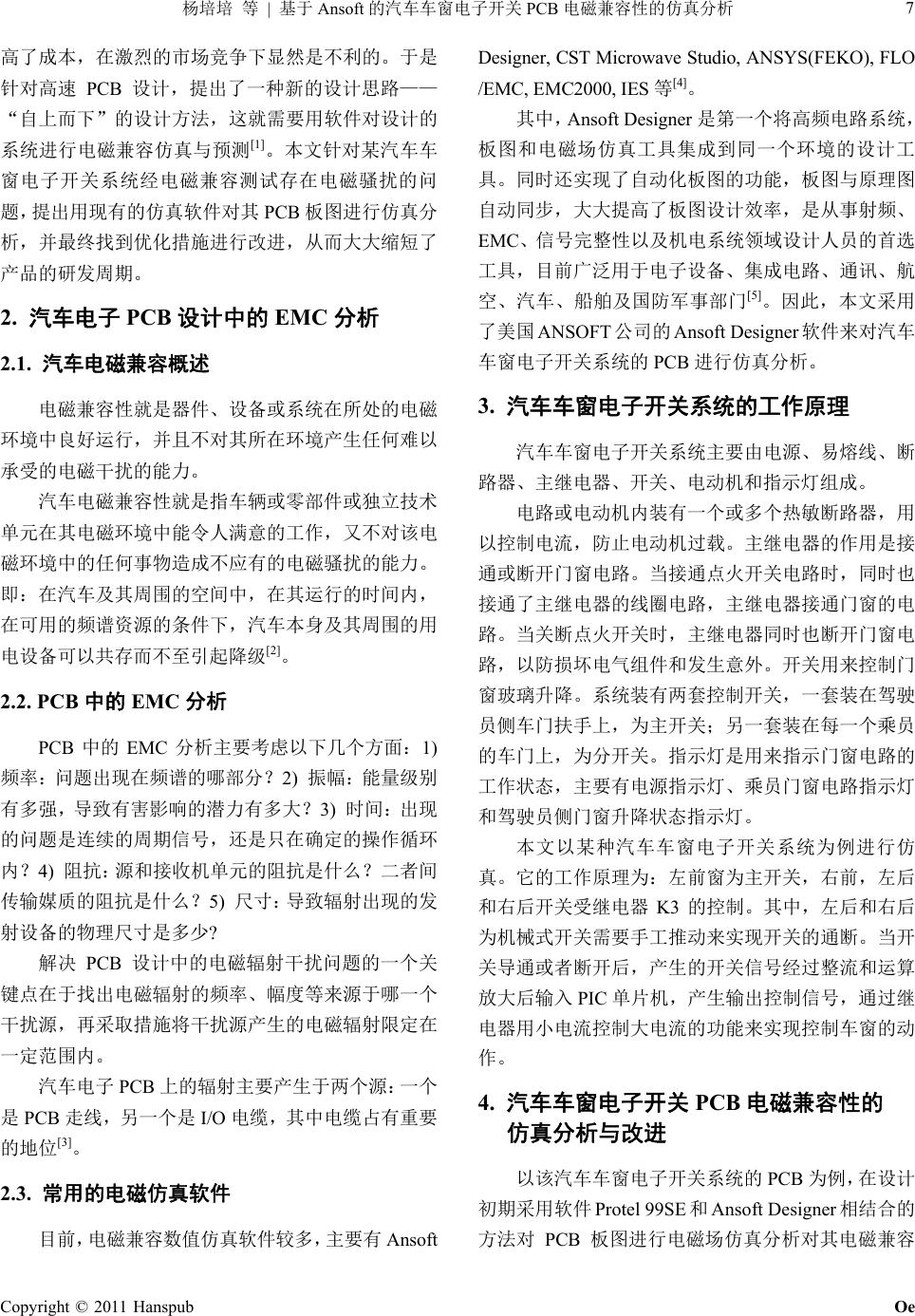 7 | Ansoft PCB PCB [1] PCB 2. 汽车电子 PCB 设计中的 EMC 分析 2.1. 汽车电磁兼容概述 [2] 2.2. PCB中的 EMC 分析 PCB EMC 1) 2) 3) 4) 5) ? PCB PCB PCB I/O [3] 2.3. 常用的电磁仿真软件 Ansoft Designer, CST Microwave Studio, ANSYS(FEKO), FLO /EMC, EMC2000, IES[4] Ansoft Designer EMC [5] ANSOFT Ansoft Designer PCB 3. 汽车车窗电子开关系统的工作原理 K3 PIC 4. 汽车车窗电子开关 PCB 电磁兼容性的 仿真分析与改进 PCB Protel 99SEAnsoft Designer PCB Copyright © 2011 Hanspub Oe 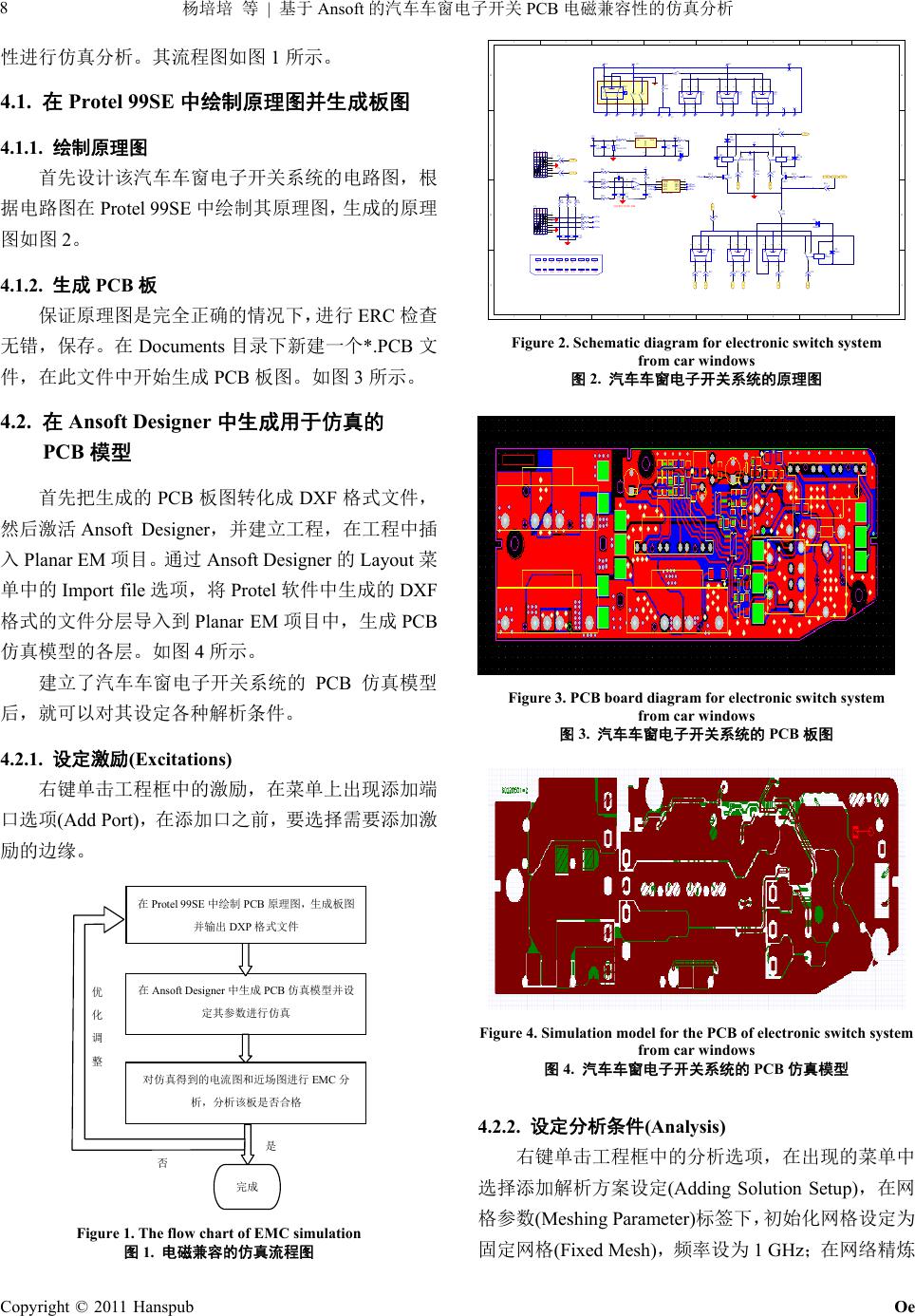 8 | Ansoft PCB Copyright © 2011 Hanspub Oe 1 4.1. 在Protel 99SE中绘制原理图并生成板图 4.1.1. 绘制原理图 Protel 99SE 2 4.1.2. 生成 PCB板 ERC Documents *.PCB PCB 3 4.2. 在Ansoft Designer中生成用于仿真的 PCB 模型 PCB DXF Ansoft Designer Planar EM Ansoft DesignerLayout Import fileProtel DXF Planar EM PCB 4 PCB 4.2.1. 设定激励(Excitations) (Add Port) Ansoft Designer PCB EMC Protel 99SEPCB DXP Figure 1. The flow chart of EMC simul ation 图1. 电磁兼容的仿真流程图 12345678 A B C D 8 7654321 D C B A 123456 789 10 1112 13 14 15161718 15 S1 4 6 1 3 7 9 10 11 12 VDD 1 GP5 2 GP4 3 GP3 4GP2 5 GP1 6 GP0 7 GND 8 U3 PIC12F508 Vin 1 GND 2 Vout 3 U1 VOLTREG C3 104 C4 104 C1 100uf C2 100uf K1 RELAY-SPDT K2 RELAY-SPDT Q1 9013 Q2 9013 D1 4007 D2 4148 D3 4148 R13 4.7k R14 4.7k 16 +5+12 UPout DNout 13 18 +12 14 17 R15 10m P1 P2 P6 P14 P10P9 P8P11 P4 P12 P13 P3 1 2 3 U2A LM2903 1 2 3 4 5 6 7 8 L1 L2 R1 R2 M J1 SW-DOOR8 1 2 3 4 5 6 7 8 L1 L2 R1 R2 M J2 SW-DOOR8 RV1 7k160/18V L1 22uH P7 UPin ATin DNin R3 10k R2 10k R4 10k R5 10k R8 10k R9 10k C9 104C10 104C11 104 +5 UPout DNout UPinATin DNin R7 10k C8 104 +5 C7 104 C6 104 C5104 R10 100k R11 100k R6 7.32k R12 180 OV OV R1 1k LED1 LED 8-10A S? S? S? 134 5 679 11 12 13 14 1516 1718 28 RV? 10m K3 HFKA D4 4148 10 4 3 5 1 2 SW1 4 3 5 1 2 SW2 4 3 5 1 2 SW3 4 3 5 1 2 SW? 4 3 5 1 2 SW? 4 3 5 1 2 SW? 4 3 5 1 2 SW? D5 IN4 0 07 Figure 2. Schematic diagram for electronic switch system from car windows 图2. 汽车车窗电子开关系统的原理图 Figure 3. PCB board diagram for electronic switch system from car windows 图3. 汽车车窗电子开关系统的 PCB 板图 Figure 4. Simulation model for the PCB of electronic switch system from car windows 图4. 汽车车窗电子开关系统的 PCB 仿真模型 4.2.2. 设定分析条件(Analysis) (Adding Solution Setup) (Meshing Parameter) (Fixed Mesh) 1 GHz 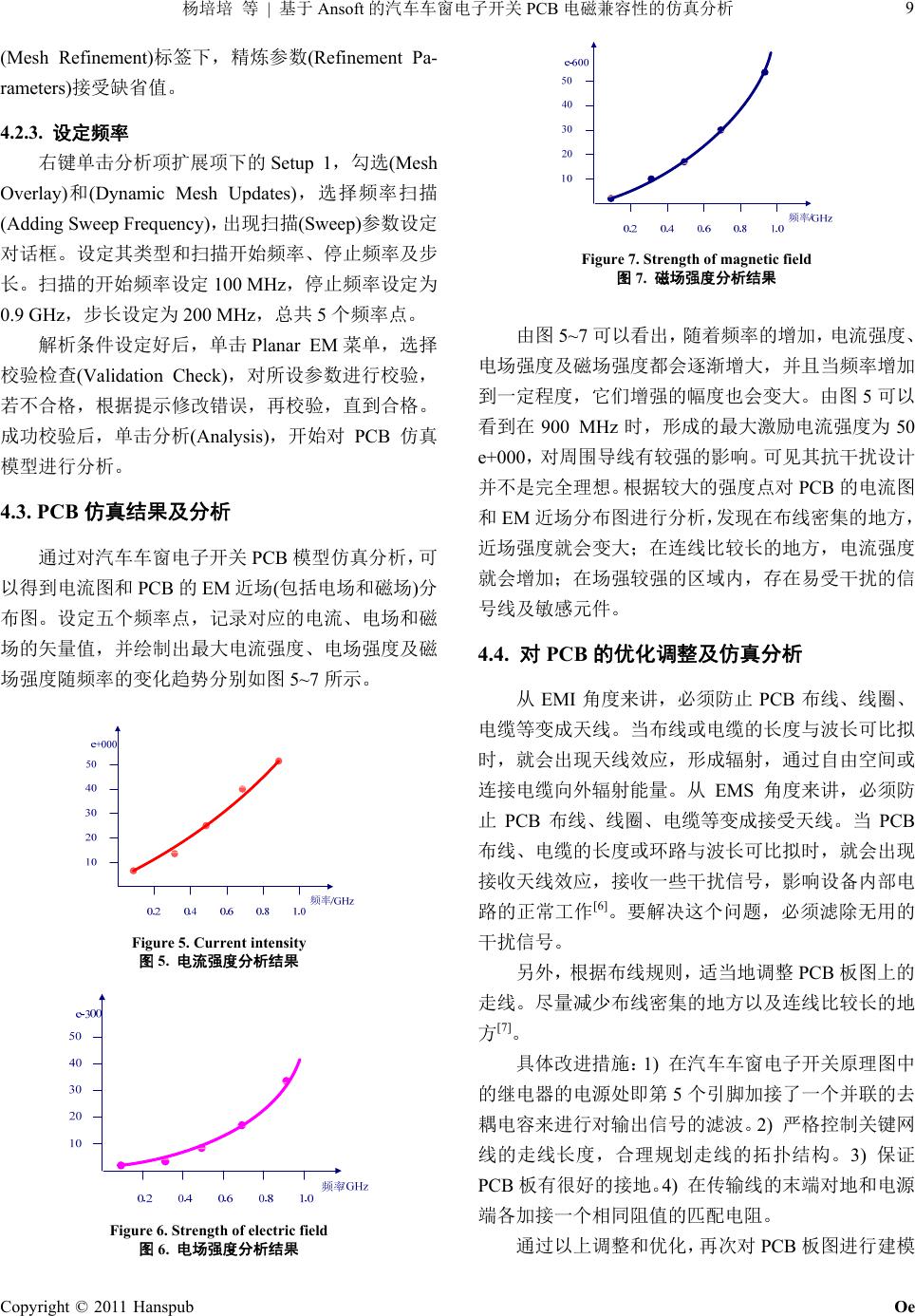 9 | Ansoft PCB Setup 1(Mesh Ove PCB (Mesh Refinement)(Refinement Pa- rameters) 4.2.3. 设定频率 rlay)(Dynamic Mesh Updates) (Adding Sweep Frequency)(Sweep) 100 MHz 0.9 GHz 200 MHz 5 Planar EM (Validation Check) (Analysis) PCB 4.3. PCB仿真结果及分析 PCB EM () 5~7 Figure 5. Current intensity 图5. 电流强度分析结果 Figure 7. Strength of magnetic field 图7. 磁场强度分析结果 5~7 调整及仿真分析 PCB 1) PCB 5 900 MHz 50 e+000 PCB EM 4.4. 对PCB 的优化 EMI PCB EMS PCB PCB [6] [7] 5 2) 3) PCB 4) Figure 6. Strength of electric field 图6. 电场强度分析结果 Copyright © 2011 Hanspub Oe 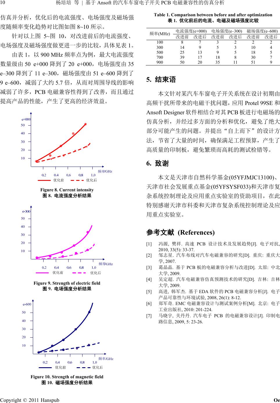 | Ansoft PCB Copyright © 2011 Hanspub Oe 10 1 e–30 8~10 5~10 1 900 MHz 50 e+000 20 e+000 35 0 11 e–300 51 e–600 9 e–600 5.7 PCB Figure 8. Current intensity 图8. 电流强度分析结果 Figure 9. Strength of electric field 图9. 电场强度分析结果 Figure 10. Strength of magnetic f ield 图10. 磁场强度分析结果 Table 1. Comparison between before a nd after optimizat ion 表1. 优化前后的电流、电磁及磁场强度比较 (e+000) (e–300) (e–600) (MHz) 100 8 7 3 2 2 2 300 14 9 5 3 10 4 500 25 13 9 5 18 5 700 39 17 18 8 30 7 900 50 20 35 11 51 9 5. 结束语 Ansoft Designer PCB 参考文献 (References) [1] , . PCB[J]. , 3(5): 33-37. . [D]. : [3] , 2008, 26(1): 8-12. [M]. : , 2010: 201-224. B[J]. Protel 99SE 6. 致谢 (05YFJMJC13100) (05YFSYSF033) 2010, 3 [2] , 2007. . PCB [D]. : , 2009. [4] . [D]. : , 2009. [5] , . EDA PCB [J]. [6] . EMC [7] , . PC , 2009, 5: 23-26. |