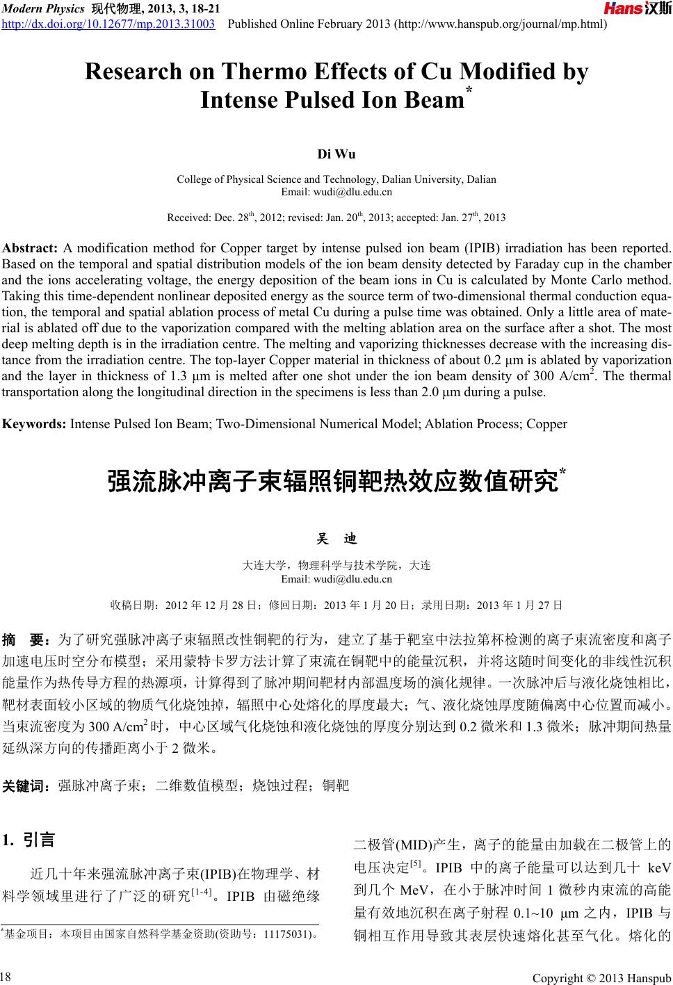
 Modern Physics 现代物理, 2013, 3, 18-21 http://dx.doi.org/10.12677/mp.2013.31003 Published Online February 2013 (http://www.hanspub.org/journal/mp.html) Research on Thermo Effects of Cu Modified by Intense Pulsed Ion Beam* Di Wu College of Physical Science and Technology, Dalian University, Dalian Email: wudi@dlu.edu.cn Received: Dec. 28th, 2012; revised: Jan. 20th, 2013; accepted: Jan. 27th, 2013 Abstract: A modification method for Copper target by intense pulsed ion beam (IPIB) irradiation has been reported. Based on the temporal and spatial distribution models of the ion beam density detected by Faraday cup in the chamber and the ions accelerating voltage, the energy deposition of the beam ions in Cu is calculated by Monte Carlo method. Taking this time-dependent nonlinear deposited energy as the source term of two-dimensional thermal conduction equa- tion, the temporal and spatial ablation process of metal Cu during a pulse time was obtained. Only a little area of mate- rial is ablated off due to the vaporization compared with the melting ablation area on the surface after a shot. The most deep melting depth is in the irradiation centre. The melting and vaporizing thicknesses decrease with the increasing dis- tance from the irradiation centre. The top-layer Copper material in thickness of about 0.2 μm is ablated by vaporization and the layer in thickness of 1.3 μm is melted after one shot under the ion beam density of 300 A/cm2. The thermal transportation along the longitudinal direction in the specimens is less than 2.0 μm during a pulse. Keywords: Intense Pulsed Ion Beam; Two-Dimensional Numerical Model; Ablation Process; Copper 强流脉冲离子束辐照铜靶热效应数值研究* 吴 迪 大连大学,物理科学与技术学院,大连 Email: wudi@dlu.edu.cn 收稿日期:2012 年12 月28日;修回日期:2013 年1月20 日;录用日期:2013年1月27 日 摘 要:为了研究强脉冲离子束辐照改性铜靶的行为,建立了基于靶室中法拉第杯检测的离子束流密度和离子 加速电压时空分布模型;采用蒙特卡罗方法计算了束流在铜靶中的能量沉积,并将这随时间变化的非线性沉积 能量作为热传导方程的热源项,计算得到了脉冲期间靶材内部温度场的演化规律。一次脉冲后与液化烧蚀相比, 靶材表面较小区域的物质气化烧蚀掉,辐照中心处熔化的厚度最大;气、液化烧蚀厚度随偏离中心位置而减小。 当束流密度为300 A/cm2时,中心区域气化烧蚀和液化烧蚀的厚度分别达到0.2 微米和 1.3 微米;脉冲期间热量 延纵深方向的传播距离小于 2微米。 关键词:强脉冲离子束;二维数值模型;烧蚀过程;铜靶 1. 引言 近几十年来强流脉冲离子束(IPIB)在物理学、材 料学领域里进行了广泛的研究[1-4]。IPIB 由磁绝缘 二极管(MID)产生,离子的能量由加载在二极管上的 电压决定[5]。IPIB 中的离子能量可以达到几十 keV 到几个 MeV,在小于脉冲时间 1微秒内束流的高能 量有效地沉积在离子射程 0.1~10 μm之内,IPIB与 铜相互作用导致其表层快速熔化甚至气化。熔化的 *基金项目:本项目由国家自然科学基金资助(资助号:11175031)。 Copyright © 2013 Hanspub 18 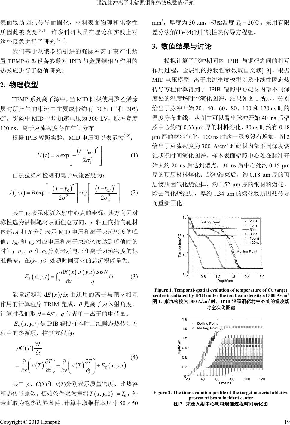 强流脉冲离子束辐照铜靶热效应数值研究 表面物质因热传导而固化,材料表面物理和化学性 质因此被改变[6,7]。许多科研人员在理论和实践上对 这些现象进行了研究[8-11]。 我们基于从俄罗斯引进的强脉冲离子束产生装 置TEMP-6 型设备参数对IPIB 与金属铜相互作用的 热效应进行了数值研究。 2. 物理模型 TEMP 系列离子源中,当 MID 阳极使用聚乙烯涂 层时所产生的束流中主要成份约有 70% H+和30% C+。实验中 MID 平均加速电压为300 kV,脉冲宽度 120 ns,离子束流密度存在空间分布。 根据 IPIB 辐照实验,MID电压可以表示为[12]: 2 0 2 1 exp 2 U tt Ut A (1) 由法拉第杯检测的离子束流密度为: 2 00 22 2 ,exp exp 22 J yy tt Jyt B 2 (2) 其中 y0表示束流入射中心点的坐标,其方向因对 称性选为沿铜靶材表面任意方向,x轴正向指向靶材 内部;A和B分别表示MID 电压和离子束流密度的峰 值;t0U和t0J对应电压和离子束流密度达到峰值时的 时间;σ1、σ和σ2分别表示电压和离子束流密度的标 准偏差。在(x,y)处随时间变化的总沉积能量为: 0 d,cos ,, d d t S Ex J yt Exyt t xq (3) 能量沉积项 dEx xd 由通用的离子与靶材相互 作用的计算程序 TRIM完成,θ是离子束入射角度, 计算时我们取θ = 45˚,q代表单一离子的电荷量。 ,, S Exyt是IPIB 辐照样本时二维瞬态热传导方 程中的热源项,控制方程为: ,, S T CT t TT TTE xxyy xyt (4) 其中 ρ、C(T)和κ(T)分别表示质量密度、比热容 和热传导系数。初始条件取为室温T 0 ,,0 xyT ,外 表面取为绝热边界条件。计算中取铜样本尺寸 50 × 50 mm2,厚度为 50 μm,初始温度T0 = 20℃。采用有限 差分法解(1)~(4)的非线性热传导方程组。 3. 数值结果与讨论 模拟计算了脉冲期间内 IPIB与铜靶之间的相互 作用过程,金属铜的热物性参数取自文献[13]。根据 MID 电压模型、离子束流密度模型以及非线性瞬态热 传导方程计算得到了 IPIB 辐照中心靶材内部不同深 度处的温度场时空演化图谱,结果如图 1所示,分别 给出了脉冲开始20、40、60、80、100和120 ns 时的 温度分布曲线。从图中可以看出脉冲开始 40 ns后辐 照中心约有 0.33 μm厚的材料熔化,80 ns 时约有 0.18 μm厚的材料气化,100 ns 时这一深度没有增加。图 2 给出了束流密度为 300 A/cm2时靶材内部不同深度烧 蚀状况时间演化图谱,样本表面辐照中心处在脉冲开 始大约 20 ns后达到熔点,30 ns后中心处约 0.15 μm 厚的顶层材料熔化;脉冲结束后,约0.18 μm厚的顶 层物质因气化烧蚀掉,约 1.52 μm厚的铜材料熔化。 除去气化烧蚀层,厚约1.34 μm的熔化物质因热传导 而重新固化。 Figure 1. Temporal-spatial evolution of temperature of Cu target centre irradiated by IPIB under the ion beam density of 300 A/cm2 图1. 束流密度为 300 A/cm 2时,IPIB辐照铜靶材中心处的温度场 时空演化图谱 Figure 2. The time evolution profile of t he targ e t material ablati v e process at beam incident center 图2. 束流入射中心靶材烧蚀过程时间演化图 Copyright © 2013 Hanspub 19  强流脉冲离子束辐照铜靶热效应数值研究 图3给出脉冲结束后铜靶材内部的熔融和气化烧 蚀状况图谱。一次脉冲后表面液化烧蚀区域比气化烧 蚀区域大很多;在靶材内部,很大区域内的靶材物质 达到气化温度,但最终没能吸收足够的气化潜热而喷 发,只有0.18 μm后的物质气化烧蚀喷发;从图中还 可以看出不论气化烧蚀还是液化烧蚀最大烧蚀处都 在辐照中心区域。图 4给出了靶材内部脉冲期间不同 时刻的熔融烧蚀等势曲线,靶材表面及内部熔融烧蚀 区域均随时间的增加而增加,脉冲结束后表面液化烧 蚀宽度达到 30 mm,纵向深度达到1.5 μm,与图 3的 结果是一致的。图 5给出脉冲辐照期间样本中心及 4.0 mm和5.0 mm偏离处的气化烧蚀时间演化图谱, 脉冲结束后中心处的最大气化烧蚀深度为0.18 μm, 偏离中心4 mm处物质脉冲结束后的最大烧蚀深度为 0.09 μm,而 5 mm处这一深度只有 0.06 μm;从图中 还可以看出靶材内部与中心偏离的某些区域永远不 会被气化烧蚀。 Figure 3. Sample material ablation distribution profile in Cu at the end of a pulse 图3. 脉冲结束后铜靶表面及内部烧蚀图 Figure 4. Sample material melting ablation curve in the Cu as a function of time during a pulse 图4. 脉冲期间靶材内部不同时间的熔融烧蚀曲线 图6给出脉冲辐照期间样本中心及10.0 mm和 15.0 mm偏离处的液化烧蚀时间演化图谱,辐照中心 在脉冲开始 20 ns 后开始熔化,偏离中心 10 mm 处则 在40 ns 后开始熔化,15 mm处则在 120 ns时才开始 熔化;脉冲结束后中心约 1.5 μm深物质熔化,这与前 面得到的结果是一致的;偏离中心 10 mm 处对应深度 约0.9 μm的靶材物质熔化,而偏离中心15 mm处则 只有表层物质脉冲结束后才熔化;从图中还可以看出 靶材内部与中心偏离的某些区域永远不会被熔融烧 蚀。图7给出了铜材内部辐照中心处及5.0 mm和 10.0 mm 偏离处的温度场演化图谱。脉冲结束后辐照中心 表面处的温度最高,深度越深温度越低;偏离中心越 远表面温度也越低;同一纵向深度处偏离中心越远温 度越低。一次脉冲后靶材温度场的等势图如图 8所示, 温度分布清晰可见,束流入射表面中心处温度最高, 一次脉冲期间沿靶材纵向深度热传导距离小于 2.0 μm。 Figure 5. The evaporating ablation evolution profile of shooting centre and at 4.0 mm and 5.0 mm distances away 图5. 脉冲期间样本中心及 4.0 mm和5.0 mm偏离处的气化烧蚀时 间演化图谱 Figure 6. The melting ablation evolution profile of irradiation centre and at 10.0 mm and 15.0 mm distances away 图6. 脉冲期间样本中心及 10.0 mm和15.0 mm偏离处的熔融烧蚀 时间演化图谱 Copyright © 2013 Hanspub 20  强流脉冲离子束辐照铜靶热效应数值研究 Copyright © 2013 Hanspub 21 Figure 7. Evolution profile of sample material temperature in the shooting centre and with 5.0 mm and 10.0 mm deviations 图7. 脉冲期间样本中心及 5.0 mm和10.0 mm偏离处的温度场时 间演化图谱 Figure 8. Temperature contour of Cu after the irradiation of IPIB under the ion beam current density of 300 A/cm2 图8. IPIB束流密度为 300 A/cm 2时一次脉冲辐照后铜靶材温度场 分布等势图 4. 结论 根据离子束流密度及 MID 电压时空分布建立了 IPIB辐照铜靶的二维瞬态热传导模型。根据模型研究 了脉冲 120 ns 期间束流辐照改性铜靶的行为。得到了 烧蚀过程中铜靶的温度场演化图谱。束流密度为300 A/cm2时,一次脉冲后表面液化烧蚀区域比气化烧蚀 区域大很多,最深熔融烧蚀处在辐照中心;靶材熔化、 气化厚度均随偏离中心位置增加而减小;脉冲结束后 约0.2 μm厚的顶层材料因气化烧蚀掉,辐照产生的纵 向熔融烧蚀厚度达到约1.3 μm;一次脉冲期间沿靶材 纵向深度的热传导距离小于2.0 μm。 参考文献 (References) [1] K. Yatsui, X. D. Kang and T. Sonegawa. Applications of intense pulsed ion beam to materials science. Physics of Plasmas, 1994, 1(5): 1730-1737. [2] J. Piekoszewski, Z. Werner and W. Szymczyk. Application of high intensity pulsed ion and plasma beams in modification of materials. Vacuum, 2001, 63(4): 475-481. [3] D. J. Rej, H. A. Davis, J. C. Olson, G. E. Remnev, A. N. Zakou- taev, V. A. Ryzhkov, V. K. Struts, I. F. Isakov, V. A. Shulov, N. A. Nochevnaya, R. W. Stinnett, E. L. Neau, K. Yatsui and W. Jiang. Materials processing with intense pulsed ion beams. Journal of Vacuum Science & Technology A, 1997, 15(3): 1089-1097. [4] W. H. Jiang, K. Ide, S. Kitayama, et al. Pulsed ion-beam evapo- ration for thin-film deposition. Japanese Journal of Applied Physics, 2001, 40(2): 1026-1029. [5] Z. Werner, J. Piekoszewski and W. Szymczyk. Generation of high-intensity pulsed ion and plasma beams for material proc- essing. Vacuum, 2001, 63(4): 701-708. [6] G. E. Remnev, I. F. Isakov, M. S. Opekounov, et al. High inten- sity pulsed ion beam sources and their industrial applications. Surface and Coatings Technology, 1999, 114(2-3): 206-212. [7] A. D. Korotaev, S. V. Ovchinnikov, Y. I. Pochivalov, et al. Struc- ture-phase states of the metal surface and undersurface layers after the treatment by powerful ion beams. Surface and Coatings Technology, 1998, 105(1-2): 84-90. [8] X. Y. Le, W. J. Zhao, S. Yan, et al. The thermodynamical process in metal surface due to the irradiation of intense pulsed ion beam. Surface and Coatings Technology, 2002, 158-159: 14-20. [9] X. D. Kang, K. Masugata and K. Yatsui. Characteristics of abla- tion plasma produced by intense, pulsed, ion beam. Japanese Journal of Applied Physics, 1994, 33(2): 1155-1160. [10] 杨海亮, 邱爱慈, 张嘉生等. “闪光二号”加速器 HPIB 的产生 及应用初步结果[J]. 物理学报, 2004, 53(2): 406-412. [11] J. L. Zhang, C. Tan, W. C. Wang and Y. N. Wang. A spectro- scopic scheme to measure the expansion velocity of ablation plasmas formed by high intensive pulsed ion beam. Vacuum, 2004, 73(3-4): 673-679. [12] D. Wu, Y. Gong, J. Y. Liu, et al. Two-dimensional numerical research on effects of titanium target bombarded by TEMP II accelerator. Chinese Physics, 2006, 15(11): 2682-2687. [13] B. Kenneth. Periodic table of elements—Copper—Cu, 2012. http://EnvironmentalChemistry.com/yogi/periodic/Cu.html |